


137001UA
2-2
Setup & Installation
3012-14-18/V24
INSTALLATION AND OPERATIONS MANUALPATTON
ELECTRONICS CO.
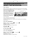
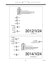
JP4 and JP5 to
ININ
ININ
IN
Provided Pin 9 and 10 Test Voltage
JP6 to
OUTOUT
OUTOUT
OUT
CTS delay = No Delay
JP1, JP2 and JP3 to
ININ
ININ
IN
Factory Test Jumpers must be installed
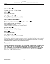
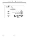
3018/V24 (CTS MSD-8C)
Switch 9 - positions 4 and 6 to
OFFOFF
OFFOFF
OFF, 1, 2, 3 and 5 to
ONON
ONON
ON
Anti-Stream = 40sec. and Disabled
Switching Mode = Priority
Signal Ground not connected to Chassis Ground
JP4 and JP5 to
ININ
ININ
IN
Provided Pin 9 and 10 Test Voltage
JP6 to
OUTOUT
OUTOUT
OUT
CTS delay = No Delay
JP1, JP2 and JP3 to
ININ
ININ
IN
Factory Test Jumpers must be installed
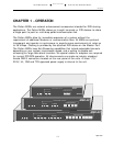
If the system application requires one or more of the default settings to be changed,
it will be necessary to remove the top cover of the enclosure to access and change
the DIP switches located on the printed circuit board.
Disassembly
Remove the top cover by unscrewing the phillips head screws located on the left and
right sides of the unit. The configuration switches and jumpers are located on the
PCB as indicated on the appropriate strapping guide in the Appendix of this manual.
After the switch selection activity is completed,
R
EINSTALL
T
HE
T
OP
C
OVER
BEFORE
C
ONNECTING
T
O
A
N
AC P
OWER
S
OURCE
.