


137001UA
2-1
Setup & Installation
PATTON
ELECTRONICS CO.
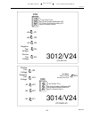
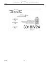
3012-14-18/V24
INSTALLATION AND OPERATIONS MANUAL
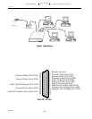
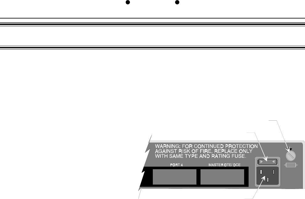
Power Connection
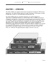
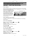
Before connecting the MSD to an AC power source the top cover must be installed
and secured with the supplied screws. The unit is supplied with a 110/220V voltage
switch. Turn the switch with a coin or
screw driver to the appropriate voltage
for your country. EXAMPLE: United
States of America, set to 110V. The
unit is supplied with an IEC power
connector next to the voltage select
switch. Plug the power cord into the
connector until it is firmly seated. You
may now connect the power cord
into your AC outlet.
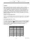
Factory Configuration Switch Settings
The MSDs are configured prior to shipment with the switches set to the following
default positions:
3012/V24 (CTS MSD-2C)
Switch 3 - positions 4, 5 and 6 to
OFF,OFF,
OFF,OFF,
OFF, 1, 2 and 3 to
ONON
ONON
ON
Anti-Stream = 40sec. and Disabled
CTS Delay = No Delay
Signal Ground not connected to Chassis Ground
JP4 and JP5 to
ININ
ININ
IN
Provide Pin 9 and 10 Test Voltage
JP1, JP2, and JP3 to
ININ
ININ
IN
Factory Testing Straps Must be installed
3014/V24 (CTS MSD-4C)
Switch 5 - positions 4 and 6 to
OFFOFF
OFFOFF
OFF, 1, 2, 3 and 5 to
ONON
ONON
ON
Anti-Stream = 40sec. and Disabled
Switching Mode = Priority
Signal Ground not connected to Chassis Ground
CHAPTER 2 - SETUP AND INSTALLATION
110 / 220VA Switch
Fuse Drawer
IEC Power Connector
110
220
Caution, Disconnect the POWER Before Removing The Cover.
Vorsicht, Befor Deckung Abnehmen Mach Strom Zu.