


Installing the SN4120 24
SmartNode 4120 User Manual 3 • SmartNode installation
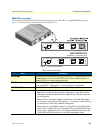
Using the included black Ethernet cable, connect the RJ-45 Ethernet WAN port on your SN4120 (labeled
ETH), to an Ethernet hub or switch on the same network as your PC.
For details on the Ethernet port pinout and cables, refer to Appendix C, “Cabling” on page 42 and Appendix
D, “Port pin-outs” on page 45.
Connecting the SN4120 to the power supply
1. Insert the barrel-type connector end of the AC power supply into the 12V DC, 1.0A port (see figure 1 on
page 16).
2. Verify that the AC power cord included with your SN4120 is compatible with local standards. If it is not,
refer to chapter 5, “Contacting Patton for assistance” on page 32 to find out how to replace it with a com-
patible power cord.
3. Connect the male end of the AC power supply power cord to an appropriate AC power outlet.
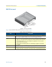
4. Verify that the green Power LED is lit (see figure 2 on page 17).
Congratulations, you have finished installing the SN4120! To configure the SN4120, go to chapter 4, “Smart-
Node initial configuration” on page 25.
The external power supply automatically adjusts to accept an
input voltage from 100 to 240 VAC (50/60 Hz).
Verify that the proper voltage is present before plugging the
power cord into the receptacle. Failure to do so could result in
equipment damage.