


6
3.0 CONFIGURATION
Note
If you have a Model 460-TBP, it does not require configuration;
refer to section 4.0, “Installation” on page 8.
The following section describes configuring the Model 460. The Model 460
Series are preset to work in most applications without additional configuration.
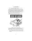
The only parameter that is user-configurable is whether there is a shield con-
nection between the 75-ohm coax and 120-ohm interfaces. Figure 1 on
page 5 shows how the shield is connected between the modular jack and dual
BNCs. Removing the jumper breaks the shield connection.
The Model 460 is most often used to bi-directionally convert CPE
twisted-pair terminations to CPE coaxial terminations.
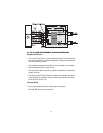
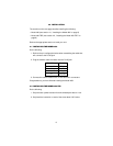
Figure 2.
JP1 and JP2 locations for 460F and 460MC
The factory setting leaves jumpers JP1 and JP2 (see Figure 2 above and
Figure 3 on page 7) in place, thus passing both shield connections
through. To change one or both of the shield connections, do the following:
1. Insert a flat-blade screwdriver into the slot on the side of the Model
460 case and twist. The case will pop open, exposing the printed cir-
cuit board.
RJ-45 (120 ohm) Jumper Coax BNC (75 ohm)
Pin 3 (TX Shield) JP1 TX Out Shield
Pin 6 (RX Shield) JP2 RX In Shield
JP1
JP2