


Connecting a PC, logging in, and configuring the LAN IP address
4
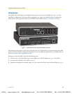
SmartNode 4830 Quick Start Guide
Connecting a PC, logging in, and configuring the LAN IP address
Connecting power and configuring the default IP address
Connect the SmartNode to the mains power supply using the included power supply and cable. When the
RUN
LED stops blinking and remains lit, the SmartNode is ready.
The factory default IP settings are listed in table 1. If these addresses do not work with your network they must
be changed. Contact your network administrator if you are not sure which IP address to use in
your installation.
Note
The DHCP server is running on the ETH 0/1 of the SN4830 Series
models. All Ethernet ports are pre-configured and active.
Connecting to a PC and logging in
1.
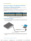
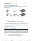
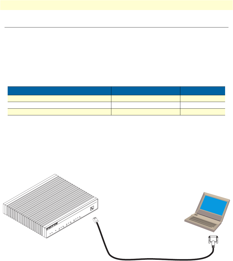
To access the SmartNode configuration, connect a PC equipped with an RS-232 console port to the
Con-
sole
port on the front of the SmartNode. Use the included black Ethernet cable and RJ45 to DB-9 adapter
for this purpose (Model 16F-561).
Figure 2. Connecting to the PC
2.
Open a Terminal connection to the SmartNode. Use the Terminal program included with most PC operat-
ing systems (e.g. Hyper Terminal on Windows). The CD-ROM also includes some recommended termi-
nal programs.
Table 1. Factory default IP address and network mask configuration
Item
IP Addresss(es) Network Mask
WAN interface Ethernet 0 (ETH 0/0)
DHCP DHCP
LAN interface Ethernet 1 (ETH 0/1) 192.168.1.1 255.255.255.0
DHCP server address range 192.168.1.10-192.168.1.19 255.255.255.0
Serial Terminal
Note
A Patton Model 16F-561 RJ45 to DB-9 adapter is included with
each SmartNode 4000 Series device
Console
VoIP Gateway Router
ToIP Integrated Access Device
SmartNode 4524
Link
100M
Activity
0/0
0/1
0/2
0/3
Enet 0 Voice Ports
Power
Run
VoIP Link
Link
100M
Activity
Enet 1
VoIPon www.voipon.co.uk sales@voipon.co.uk Tel: +44 (0)1245 808195 Fax: +44 (0)1245 600030