


12
5.0 INSTALLATION
Once the Model 2707/I is properly configured, it is ready to connect to
the G.703 interface, to the Ethernet port, and to the power source. This
section describes how to make these connections.
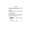
5.1 CONNECTING TO THE G.703 NETWORK AND ETHERNET LAN
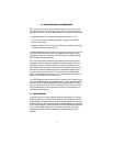
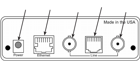
This section describes installing the G.703 (75-ohm and 120-ohm),
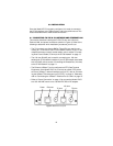
Ethernet LAN, and power connections (shown in Figure 4). Refer to the
following to detemine which installation procedures you will use:
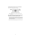
• The 75-ohm dual-coax female BNCs (TXand RX) are used for con-
necting to a 75-ohm dual coax G.703 network interface. If your G.703
network terminates via dual coaxial cables, refer to section “Connect-
ing Dual Coaxial Cable (75 ohm) to the G.703 Network” on page 13
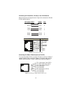
• The 120-ohm RJ-48C jack is used for connecting to a 120-ohm
twisted-pair G.703 network interface. If your G.703 network terminates
with a RJ-48C, refer to section “Connecting the Twisted Pair (120 ohm)
to the G.703 Network” on page 14.
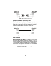
• The Ethernet 10Base-T port is configured as DTE (Data Terminal
Equipment). If the Model 2707/I is to connect to another DTE device
such as a 10Base-T network interface card in a PC, refer to “Connect-
ing the 10Base-T Ethernet port to a PC (DTE)” on page 14. Otherwise,
refer to “Connecting the 10Base-T Ethernet Port to a Hub” on page 15.
• Refer to “Power Connection” on page 15 to connect the Model 2707/I
to a 100–240 VAC source or to a 36–60 VDC DC-to-DC adapter.
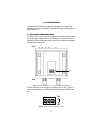
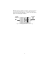
Figure 4.
Model 2707/I rear panel
75 ohm
120 ohm
TX
RX
75 ohm
EthernetPower