


9
4.0 CONFIGURATION
The Model 2707/I features configuration capability via hardware DIP
switches. This section describes all possible DIP switch configurations of
the Model 2707/I.
4.1 DIP SWITCH CONFIGURATIONS
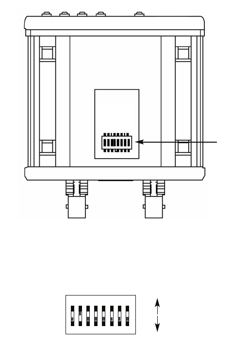
The Model 2707/I has an internal DIP switch that enables configuration
for a wide range of applications. The DIP switch is accessed from the
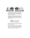
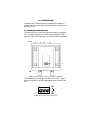
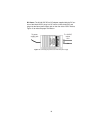
underside. Figure 2 shows the location of the DIP switches on the bottom
of the printed circuit board.
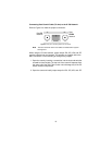
Figure 2.
Underside of Model 2707/I, showing location of DIP switches
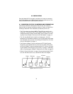
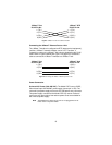
The DIP switches can be configured as either “ON” or “OFF”. Figure 3
shows the orientation of the DIP switches with respect to ON/OFF posi-
tions.
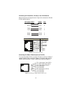
Figure 3.
Close-up view of configuration switches
Front
Rear
S1
12345678
DHS-8
OF
F
ON
ON
OFF