


17
6.0 OPERATION
When the Model 2707/I has been properly configured and installed, it
should operate transparently. This section describes power-up, LED sta-
tus monitors, and the built-in loopback test modes.
6.1 POWER-UP
Before applying power to the Model 2707/I, please review section “Power
Connection” on page 15 to verify that the unit is properly connected to
the appropriate power source.
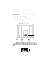
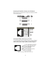
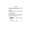
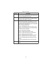
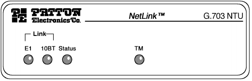
6.2 LED STATUS MONITORS
The Model 2707/I features six front panel LEDs that monitor connections
on the G.703 and 10Base-T links, signaling, error and test modes.
Figure 11 shows the front panel location of each LED. Table 2 on
page 18 lists descriptions of each LED.
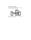
Figure 11.
2707/I front panel
10Base-T