


11
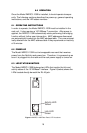
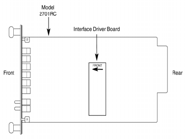
4.1 CONNECTING THE INTERFACE DRIVER BOARD
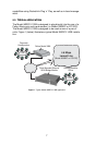
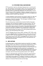
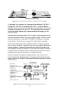
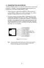
This package contains an interface driver board that allows you to config-
ure your front function card for ethernet operation. Figure 4 shows the
Interface Driver Board connected to a Model 2701RC front function card.
Figure 4. Model IM2RC/I-100B Driver Board mounted on Model 2701RC
Follow the instructions below to connect the interface driver board to the
front function card:
1. With the function card (such as 2701RC, shown above) pulled out of
the NetLink rack or clusterbox chassis, locate the driver board to be
replaced on the top of the base unit front card.
2. Lift the old interface board gently off of the printed circuit board.
3. Position the IM2RC/I-100B driver board on top of the function card’s
pc board with the sockets oriented toward the male pins. Please be
sure the label marked FRONT <– is pointed toward the front of the
function card (toward the LEDs).
4. Push the Interface Driver Board gently onto the socket and re-install
the function card into the rack or cluster system.