


16
6.0 OPERATION
Once the Model IM2RC/I-100B is installed, it should operate transpar-
ently. The following sections describes the power-up, general operating
instructions, and the LED status monitors.
6.1 OPERATING INSTRUCTIONS
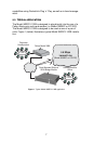
In order to operate, the Model IM2RC/I-100B must be installed in the
rack unit. It also requires a 10/100Base-T connection. After power is
applied, the IM2RC/I-100B automatically starts performing the bridging
function without further user intervention. MAC addresses discovered
are automatically loaded into the MAC address table. They are automat-
ically deleted from the MAC address table if they experience an inactivity
of 8 minutes.
6.2 POWER-UP
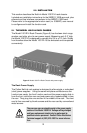
The Model IM2RC/I-100B is a hot-swappable rear card that receives
power from the NetLink rack power bus. Therefore, it is powered up as
soon it is plugged into the rack and the rack power supply is turned on.
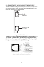
6.3 LED STATUS MONITORS
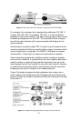
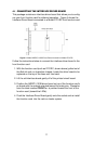
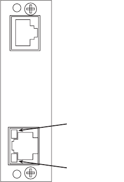
The Model IM2RC/I-100B features two LEDs that monitor the link and
activity status of the 10/100BaseT interface. Figure 9 (below) shows the
LEDs located directly beneath the RJ-45 jack.
Figure 9. IM2RC/I-100B Rear Panel, LED Locations
Activity LED
Yellow
Link LED
Green