


15
5.4 CONNECTING THE LINE INTERFACE
The Model IM2RC/I-100B is to be used with Patton function card access
products (i.e. 3088RC) There are two essential requirements for con-
necting the line interface on Model IM2RC/I-100B:
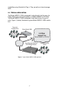
1. These units work in pairs with one IM2RC/I-100B connected to
another IM2RC/I-100B over 2 or 4-Wire Twisted pair (2 or 4-Wire
operation is determined by the front function card).
2. To function properly, the Model IM2RC/I-100B needs one or two
twisted pairs of metallic wire (two or four wire). The twisted pairs
must be unconditioned, dry, metallic wire, between 19 (.9mm) and
26 AWG (.4mm) (Appendix B describes cable requirements). Stan-
dard dial-up telephone circuits, or leased circuits that run through
signal equalization equipment, or standard, flat modular telephone
type cable, are not acceptable.
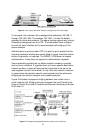
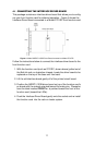
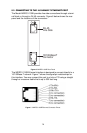
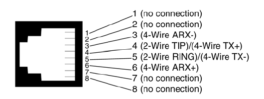
Figure 8. RJ-45 Line Interface
Note Two-wire modems use RJ-45 pins 4 and 5 and 4-wire modems
use RJ-45 pins 3, 4, 5 and 6, as shown above. Refer to the
Function Card User Manual for more details.