2.3.1 APPLICATIONS AND ASSOCIATED TIMING
There are two typical applications that result in two different timing
modes for the G.703 interface. These are illustrated below.
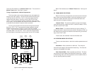
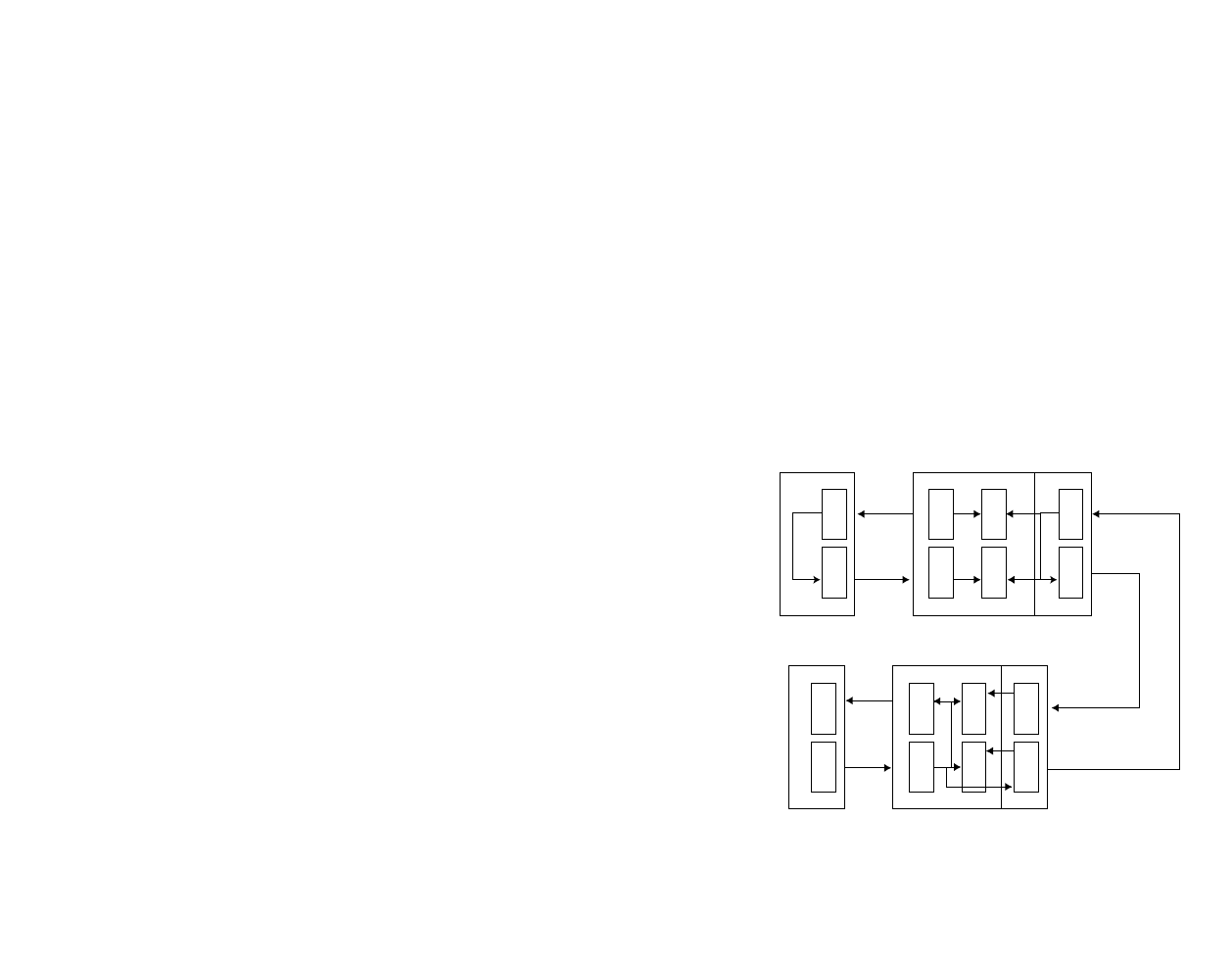
Timing of Application 1: Network Loop Extension
In this application, the network supplies the timing for the entire
system. The first G.703 recovers the timing. It has to smooth the
clock before it supplies the clock (XCLK1) and the data (TXD1) to the
first modem transmitter, so it can directly use the clock. The Rx of the
second modem recovers the clock and presents a “jittery” clock
(RXCLK1) and data (RXD1) to the second G.703’s transmitter. This
transmitter has to smooth the clock before it uses the clock to transmit.
The Rx of the second G.703 recovers the timing and clocks the
data into a FIFO. The Tx of the second modem takes its recovered
clock and sends it (TXCLK1) to the G.703 FIFO for data (TXD1). The
Rx of the first modem recovers the timing and clocks (RXCLK1) the
data (RXD1) into a FIFO. The Tx of the first G.703 uses the first
G.703’s recovered clock and sends it to the FIFO for data.
2.0 GENERAL INFORMATION
Thank you for your purchase of this Patton Electronics product.
This product has been thoroughly inspected and tested and is warrant-
ed for One Year parts and labor. If any questions or problems arise
during installation or use of this product, please do not hesitate to con-
tact us at: (301) 975-1007, http://www.patton.com; support@pat-
ton.com.
2.1 FEATURES
• Designed for use with Patton Electronics Access products that
receive QuickConnect
TM
Modules and support 64K or 128K syn-
chronous rates.
• Provides 64K codirectional interface compliant with the G.703
electrical specs.
• Offers a single Tx/Rx interface with a standard RJ-45 connector as
specified in TBR 14.
• Option to work in two timing modes: Clear channel or octet timing.
• Complies with ITU/CCITT G.823 (Control of Jitter).
• Point-to-point distance up to 4,000 feet (1219m) using 24 AWG
twisted pair.
• Made in the U.S.A.
2.2 DESCRIPTION
The Patton Model IM 1/F Interface Module converts data from a
64K G.703 network into a Transistor-Transistor Logic (TTL) compatible
signal that is transported by the PE 1090 or 1092 Modem or a similar 2
or 4 wire short haul modem that has identical pin outs and edge con-
nector style (see note, below). The G.703 network provides a 64K co-
directional three level signal using either octet timing or clear channel
mode. The IM will detect and pass either octet timing (preserving byte
integrity over a 128kbps modem link) or clear channel timing (without
byte integrity preservation) over a 64Kbps modem link. The IM is
capable of handling either network timing or modem timing, thereby
realizing network extension or network replacement configurations.
Clock jitter is attenuated according to G.823.
2.3 SYSTEM DESCRIPTION
This section describes the features that the entire system (G.703
interface, combined with the modems) will support.
NOTE: The “smoothed” clocks referred to in this section indicate
that a phase locked VCO is used to create a jitter free clock that is
locked to a source clock.
3
4
Figure 1. Network Loop Extension Configuration
RX
TX
CSU
DTE
G.703
RX
RX
RX
RX
RX
2 or 4 Wire
TX
G.703 INTF-
MODEM
TIMED MODE
SECOND MODEM
FIFO
TX
SMOOTHED
TX
TX
TX
FIFO
FIFO
G.703
FIFO
HOST
MODEM -
RECOVERED
TIMING
FIRST MODEM
HOST
MODEM -
INTERFACE
(EXTERNAL)
TIMING
G.703 INTF-
NETWORK
TIMED MODE
NETWORK
G.703 TX
SMOOTHS
RX MODEM
CLOCK


