


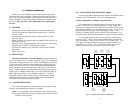
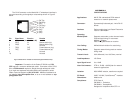

The RJ-45 connector on the Model IM 1/F twisted pair interface is
pre-wired according to the signal/pin relationships shown in Figure 5
below.
Important: Connection of the Patton G.703 IM to a CSU
DTE requires a crossover twisted pair cable. Connection of the G.703
IM to a PCM network requires a straight through twisted pair cable.
If you need more assistance with cable selection and preparation, contact
Patton Technical Support at (301) 975-1007. Additional assistance at
our website, http://www.patton.com, or at our e-mail address at sup-
port@patton.com.
APPENDIX A
SPECIFICATIONS
Applications: 64K G.703 codirectional PCM network
extension or network replacement
Connector: Symmetrically balanced pair, 4 wire RJ-45
female
Interface: Entire module plugs into Patton Electronics
1090 or 1092 Modem
Operating
Modes/Speed: Supports octet mode or clear channel mode
Co-directional timing, Rx recovered:
64Kbits +
500ppm
Octet Timing auto detect on receiver
Line Coding: AMI with block violation for octet timing
Timing Modes: Supports network timing mode or modem
timing mode
Transmit Level: 2.0V differential, into 100 Ohms, nominal
Load Impedance: 120 Ohms
Input Signal Level: 0 to -10dB
Jitter Performance: CTR 14, G.823. <0.05UI jitter for network
extension applications
Isolation: 2000 VRMS isolation, transformer coupled
PC Board 2.950” X 3.200”, QuickConnect
TM
Interface
Dimensions: Module size
Compliance: FCC Class A
EN 50081-1, Emissions
EN 50082-1, Susceptibility
Designed for compliance with CTR 14
9 10
1 (RX Tip)
2 (RX Ring)
3 (N/C)
4 (TX Ring)
5 (TX Tip)
6 (N/C)
7 (N/C)
8 (N/C)
1
2
3
4
5
6
7
8
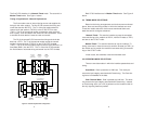
Pin Signal Name Direction Function
(In reference to IM)
1 RD(T) IN Receive data in (tip)
2 RD(R) IN Receive data in (ring)
3 Not used
4 TD(R) OUT Transmit data out (ring)
5 TD(T) OUT Transmit data out (tip)
6 Not used
7,8 Not used
Figure 5. Model IM 1/F Twisted Pair Interface Signal/Pin Relationship