


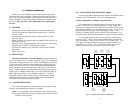
3.0 CONFIGURATION
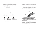
The Model IM 1/F is equipped with four DIP switches that allow
configuration of the unit to match your application. These DIP switch-
es are located on the top side of the module. Refer to Figure 3 below
for a description of the DIP switches location on the module and a
summary table detailing their settings.
The following table defines the possible configurations of the IM
1/F using the configuration DIP switch, S1. Factory defaults are in
bold-face.
Switch
On Off
S1-1 Modem Timed Network Timed
S1-2 Not Used Not Used
S1-3 Clear Channel Mode Octet Mode
S1-4 Normal Operation Reserved for Factory
Use
NOTE: S1-4 must be “On.”
7
Figure 3: Top Side of IM 1/F, Dip Switch Location
4 3 2 1
On
Off
4.0 INSTALLATION
Once the Model IM 1/F is properly configured, it is ready to install into a
PE 1090 or 1092. This section tells you how to properly connect the Model IM
1/F.
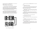
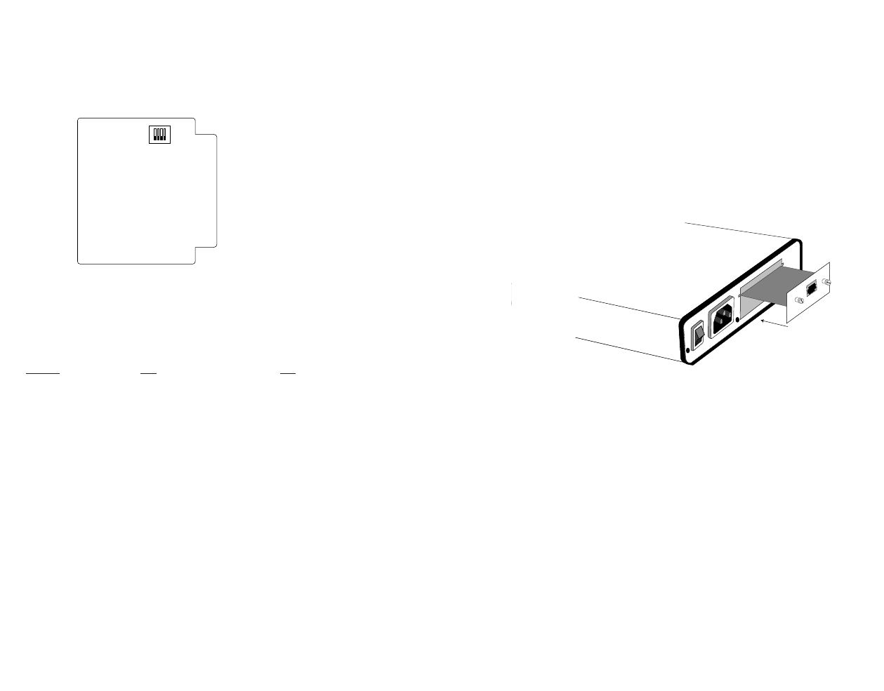
4.1 CONNECTION TO THE MODEM’S SERIAL PORT
The QuickConnect
TM
module has a 50 pin card edge connector on
one side and an RJ-45 connector on the other side. Figure 4 shows
how a QuickConnect
TM
module plugs into the back of a Patton
Electronics Model 1090 or Model 1092.
4.2
CONNECTION TO THE TWISTED PAIR INTERFACE
The Model IM 1/F supports communication between itself and a
G.703 PCM network at distances up to 4,000 feet (1219m) using 24
AWG twisted pair cable.
To function properly, the Model IM 1/F requires two twisted pairs
of metallic wire. These twisted pairs must be unconditioned, dry metal-
lic wire, between 22 and 26 AWG (0.4mm to 0.6mm diameter solid
conductors). Higher gauge wire may limit distance. Flat modular tele-
phone type cable is not acceptable.
8
0 OFF
1 ON
Line
Interface Port
Figure 4. Installation of Model IM 1/F Plug-in Serial Interface Module