


3.0 CONFIGURATION
The Model 1012AR is pre-configured at the factory to work in mul-
tipoint applications, and in point-to-point applications that use hardware
flow control. These are the vast majority of applications that call for
the Model 1012AR. Therefore, you will normally have no need to re-
configure the Model 1012AR: it will be strictly “plug-and-play”.
The only user-modifiable setting on the Model 1012AR is the RTS
control strap. The RTS control strap setting determines how its trans-
mitter (i.e. carrier) is activated. When the RST control strap is ON
(installed on the pins), the transmitter is enabled by activating RTS
(RJ-45 pin 8). This is the
factory setting
.. When its strap is OFF
(removed from the pins), the 1012AR’s transmitter is constantly on. If
your application requires the transmitter to be constantly on (i.e. hard-
ware flow control disabled), follow the instructions below:
Step 1: Opening the Case. To open the Model 1012AR’s case,
insert the blade of a small flat-head screw driver into the narrow slots
on either side of the case and twist. The two case halves should pop
apart. Then slide the case halves off of the two end inserts. This will
expose the PC board.
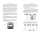
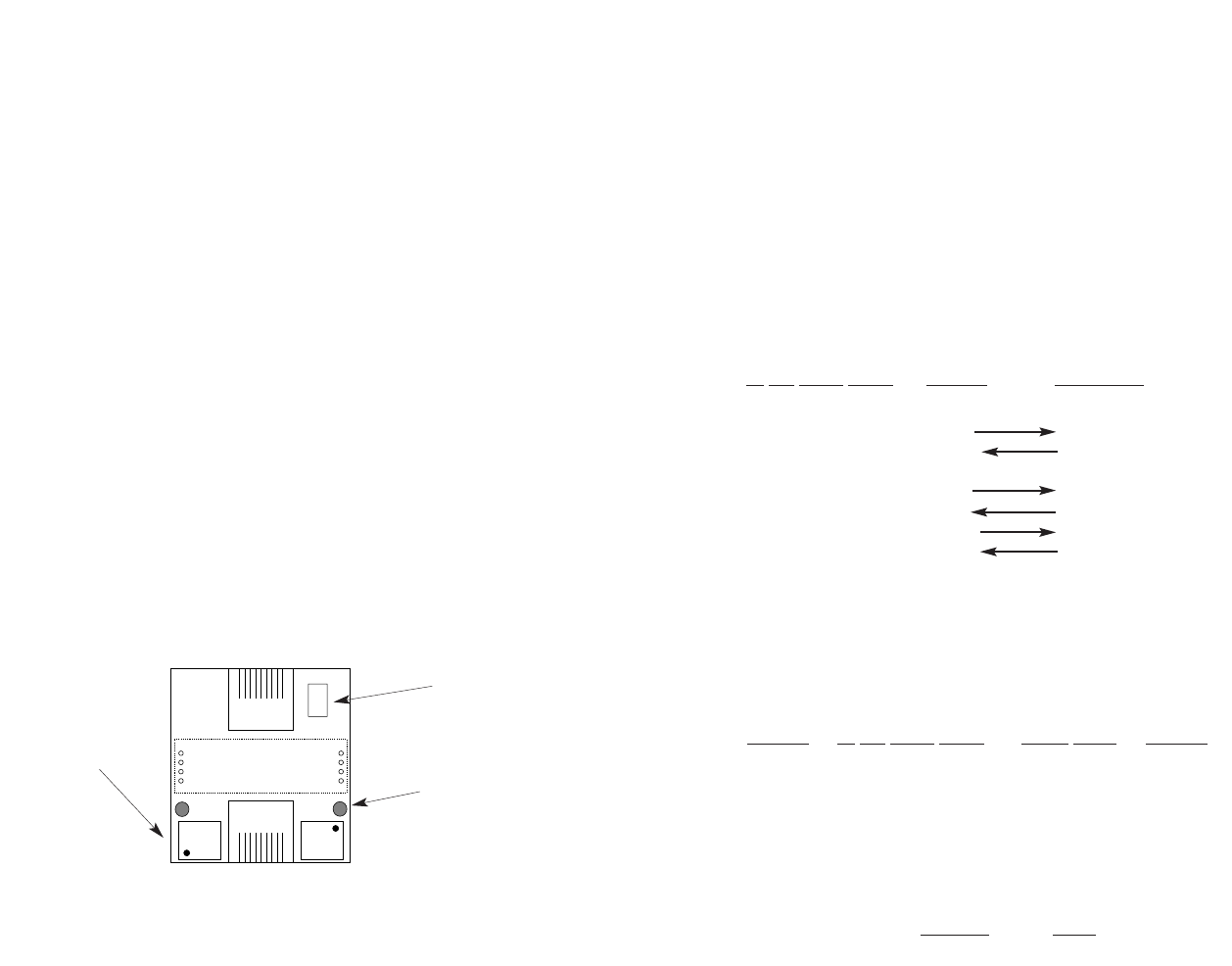
Step 2: Setting the RTS Strap. On Figure 1 (below), you will
see the location of the RTS strap on the PC board. To re-configure the
Model 1012AR for transmitter constantly on, remove the strap by
pulling it out with a pair of needle-nose pliers or tweezers. Be sure not
to lose the strap.
Step 3: Closing the Case. To close the Model 1012AR’s case,
be sure the end inserts are in place around th modular jacks
(“side”side closest to the clip) and slide th case halves down around
them. Then snap the case halves shut.
4.0 INSTALLATION
The Model 1012AR features modular connectors on both the
EIA/TIA-561 and 4-wire (line) sides. The EIA/TIA-561 interface is
always a
10 pin
RJ-45 jack (although its physical size is identical to an
8-pin RJ-45 jack). A one foot RJ-45 patch cable, wired straight
through, is supplied with the unit. The 4-wire interface may be a 6 pin
RJ-11 jack or an
8 pin
RJ-45 jack.
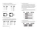
4.1 CONNECTION TO THE EIA/TIA-561 INTERFACE
The Model 1012AR features a convenient, 10 pin RJ-45 jack for
interface with your DTE device. This jack is wired as a DCE accord-
ing to the EIA/TIA-561 specification. Figure 2 (below) shows the
pins and signals for the modular EIA/TIA-561 interface. Note: Signal
are
named
from the perspective of the DTE (PC/terminal). Therefore,
even though pin 7 (below) is called “TD” , the signal is actually
incom-
ing
to the DCE (Model 1012AR).
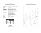
10 Pin RJ-45 (DCE) SIGNAL DIRECTION
1 ----------------------N/C
2 ----------------------RI Not Supported
3 ----------------------CD From 1012AR
4 ----------------------DTR To 1012AR
5 ----------------------SG No Direction
6 ----------------------RD From 1012AR
7 ----------------------TD To 1012AR
8 ----------------------CTS From 1012AR
9 ----------------------RTS To 1012AR
10 ----------------------N/C
.
Figure 2. Pin-outs for the Model 1012AR’s modular EIA/TIA-561 interface jack
If you wish to use the Model 1012AR with a DTE device that is
equipped with a DB-25 RS-232 port, you will need to construct a
patch cable according to the diagram shown in Figure 3 (below).
SIGNAL
10 Pin RJ-45 (DCE) DB-25 (DTE) SIGNAL
CD 3 ------------------------------8 CD
DTR 4 ------------------------------20 DTR
SG 5 ------------------------------7 SG
RD 6 ------------------------------3 RD
TD 7 ------------------------------2 TD
CTS 8 ------------------------------5 CTS
RTS 9 ------------------------------9 RTS
Figure 3. Pin connections for an EIA/TIA-561(RJ-45) to RS-232 (DB-25) patch cable.
3 4
Surge
Suppressors
Isolation
Transformers
RTS/CTS
Strap
Figure 1. Model 1012AR board, showing the RTS strap location