


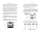
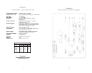
4.2 CONNECTION TO THE 4-WIRE INTERFACE
The Model 1012AR offers RJ-11 and RJ-45 options for connection
of the 4-wire data line. The signals/pins used are shown below:
RJ-1
1 SIGNAL RJ-45 SIGNAL
1 ------------GND
†
1 -----------N/C
2 ------------RCV- 2 -----------GND
3 ------------XMT+ 3 -----------RCV-
4 ------------XMT- 4 -----------XMT+
5 ------------RCV+ 5 -----------XMT-
6 ------------GND 6 -----------RCV+
7 -----------GND
8 -----------N/C
†
Connection to ground is optional
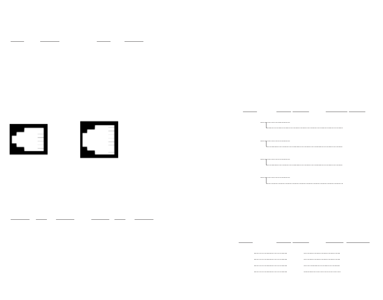
4.2.1 POINT-TO-POINT CONNECTION
When installing two Model 1012AR units in a point-to-point appli-
cation, the cable between them should be a
crossover
cable, as shown
in the following chart. The color/pin number correlations below corre-
spond to AT&T’s wiring standard for RJ-11 connectors.
SIGNAL
PIN# COLOR COLOR PIN# SIGNAL
GND
†
1 Blue
‡
--------------White 6 GND
RCV- 2 Yellow------------Red 4 XMT-
XMT+ 3 Green ------------Black 5 RCV+
XMT- 4 Red---------------Yellow 2 RCV-
RCV+ 5 Black -------------Green 3 XMT+
GND 6 White-------------Blue 1 GND
†
Connection to ground is optional
‡
Standard color codes—yours may be different
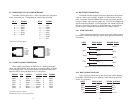
4.3 MULTIPOINT CONNECTION
The Model 1012AR supports multi-point applications using either
a star or a daisy chain topology. together in a master/slave arrange-
ment. Maximum distance between the units will vary based upon the
number of drops, data rate, wire gauge, etc. Call Technical Support for
specific distance estimates. In both topologies, the master unit should
be set to “transmitter constantly on” (strap removed), and the slaves
should be set to “transmitter controlled by RTS” (strap in place).
4.3.1 STAR TOPOLOGY
Figure 4 (below) shows how to wire the two-pair cables properly
for a Model 1012AR star topology. Note that the ground connection is
not needed
4.3.2 DAISY CHAIN TOPOLOGY
Figure 5 (below) shows how to wire the two-pair cables properly
for a Model 1012AR daisy-chain topology. Note that the ground con-
nection is not needed.
5 6
1 - Blue
2 - Orange
3 - Black
4 - Red
5 - Green
6 - Yellow
7 - Brown
8 - Slate
1 - Blue
2 - Yellow
3 - Green
4 - Red
5 - Black
6 - White
HOST FIRST SLAVE SECOND SLAVE
XMT+ RCV+
RCV+
XMT- RCV-
RCV-
RCV+ XMT+
XMT+
RCV- XMT-
XMT-
Figure 4. Star wiring for Model 1012AR host and slaves
HOST FIRST SLAVE OTHER SLAVE(S)
XMT+ RCV+ RCV+
XMT- RCV- RCV-
RCV+ XMT+ XMT+
RCV- XMT- XMT-
Figure 5. Daisy chain wiring for Model 1012AR host and slaves