


17
18
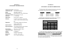
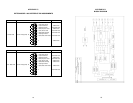
APPENDIX E
TROUBLESHOOTING
SYMPTOM PROBLEM SOLUTION
"TD" and "RD" LEDs
indicate activity, but
units will not
communicate or
data is garbled
"TD" and "RD" LEDs
indicate activity, but
"CD" LED is unlit or
red (should be
green)
Occasional data
errors
1. Improper RS-232
wiring
2. Improper twisted
pair wiring
3. Improper bit rate
setting
1. Defective twisted
pair line
2. Poor twisted pair
connections to Model
1060s
1. Distance/bit rate
capacity exceeded
2. Poor quality twisted
pair circuit
3. Poor twisted pair
connections to Model
1060s
1. Check wiring
between Model 1060
and connected serial
device—it should be
straight through
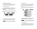
2. Compare your
twisted pair wiring with
the diagram in Section
4.1
3. Make sure the bit
rates on all connected
serial devices are the
same
1. Test continuity of
twisted pair line
2. Check screw
terminal/RJ-11
connections to Model
1060s; check integrity
of plug RJ-11
terminations
1. Check specifications
in Appendix B
2. Use a different
twisted pair circuit if
available
3. Check screw
terminal/RJ-11
connections to Model
1060s; check integrity
of plug RJ-11
terminations
APPENDIX E
TROUBLESHOOTING (CONTINUED)
SYMPTOM PROBLEM SOLUTION
LEDs do not light
when AC power
transformer is
plugged into wall
No data transfer in
either or both
directions
1. The AC transformer
is not plugged into the
Model 1060
2. Loose power
connection
3. Outlet is defective
4. AC power adapter
is defective
1. Improper twisted
pair wiring
2. Improper DCE/DTE
setting
3. Improper bit rate
setting
4. Improper
"control input" pin
setting
5. Distance
specifications
exceeded
1. Have another cup of
coffee!
2. Make sure the AC
connection is flush
3. Try a different outlet
4. Call Patton
Electronics for a
replacement adapter
1. Compare your
twisted pair wiring with
the diagram in Section
4.1
2. Set both DCE/DTE
switches alike,
according to the
instructions in Section
3.2
3. Be sure all bit rate
settings on all
connected serial ports
are the same
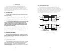
4. The transmitter must
be enabled by a
specific "control input"
pin (refer to Table 1 in
Section 3.3)
5. Check specifications
in Appendix B