


Control Input (C
in
):
The Control Input signal is used by the local Model 1060 as an
input signal to activate its transmitter (“Enabled” settings) and allow
data transmission to the remote device. This is required for half-duplex/
switched-carrier environments as well as in hardware flow control
applications. In the “Disabled” settings, the 1060 is always “turned on”
and sends a continuous carrier to the remote 1060.
Control Output (C
out
):
The Control Output signal is transmitted by the local Model 1060
to its attached DTE device. This signal should be the same logic state
as the Control Input signal on the remote 1060. This signal is required
in half-duplex/switched carrier environments or in hardware flow control
applications.
+Voltage Output (+V
out
):
The +Voltage Output signal is a constant positive voltage that is
sent from the 1060 to its attached DTE device.
Carrier Controlled by (C
in
):
When Carrier Controlled by Control Input is “Enabled”, the Model
1060’s transmitter is activated by the corresponding C
in
Signal from the
DTE. In effect, the Control Input signal on the local 1060 "controls" the
presence of "carrier" and the Control Output signal on the remote 1060.
This setting is required in half-duplex/switched carrier environments or
in hardware flow control applications. When Carrier Control by Control
Input is “Disabled”, the 1060 sends a continuous carrier and is always
“turned on”.
6
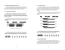
3.1.2 MULTIPOINT CONFIGURATION
The Model 1060 supports multipoint operation in either daisy chain
or star configurations. For multipoint configuration and wiring
information, refer to Section 4.2, pages 7.
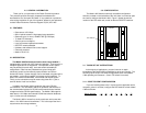
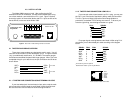
3.2 DCE/DTE SWITCH SETTINGS
Correct setting of the DCE/DTE switches eliminates the need for
RS-232 crossover cables. If the RS-232 device you are connecting to
the Model 1060 is a PC, terminal or host, or is wired like one, set
both
of the DCE/DTE switches to "DCE". If the RS-232 device you are
connecting to the Model 1060 is a modem or multiplexer, or is wired like
one, set
both
of the DCE/DTE switches to "DTE".
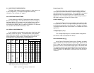
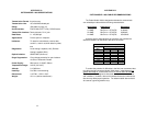
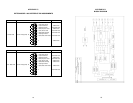
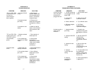
3.3 SPECIAL CONFIGURATION
If your installation requires special configuration of the Model 1060,
use Table 1 (below) as a guide. This table shows all of the possible
Model 1060 switch settings. Following the table are brief descriptions
of the Control Input, Control Output, +Voltage Output and Carrier
Controlled by (C
in
) parameters shown in the table below.
*Multiple input pins are "or-tied"—if any input goes low, carrier is dropped
**Multiple output pins generate the same signal simultaneously
Table 1. All possible switch settings for the Model 1060
5
DCE 4 8 6 Disabled ON ON ON OFF OFF OFF OFF
DCE 4 8 6 Enabled ON ON ON OFF OFF OFF ON
DCE 4,11,20* 8 6 Disabled OFF ON ON ON OFF OFF OFF
DCE 4,11,20* 8 6 Enabled OFF ON ON ON OFF OFF ON
DCE 4 6 8 Disabled ON OFF OFF OFF ON ON OFF
DCE 4 6 8 Enabled ON OFF OFF OFF ON ON ON
DCE 4,11,20* 6 8 Disabled OFF OFF OFF ON ON ON OFF
DCE 4,11,20* 6 8 Enabled OFF OFF OFF ON ON ON ON
DTE 8 4 11,20** Disabled ON ON ON OFF OFF OFF OFF
DTE 8 4 11,20** Enabled ON ON ON OFF OFF OFF ON
DTE 5,6,8* 4 11,20** Disabled OFF ON ON ON OFF OFF OFF
DTE 5,6,8* 4 11,20** Enabled OFF ON ON ON OFF OFF ON
DTE 8 11,20** 4 Disabled ON OFF OFF OFF ON ON OFF
DTE 8 11,20** 4 Enabled ON OFF OFF OFF ON ON ON
DTE 5,6,8* 11,20** 4 Disabled OFF OFF OFF ON ON ON OFF
DTE 5,6,8* 11,20** 4 Enabled OFF OFF OFF ON ON ON ON
Control Control +Voltage Carrier
Mode Input Output Output Controlled
(DCE/DTE) (C
In
)(C
Out
)(V
Out
) by (C
In
) 1234567
Switch Settings