


2.0 GENERAL INFORMATION
Thank you for your purchase of this Patton Electronics product.
This product has been thoroughly inspected and tested and is
warranted for One Year parts and labor. If any questions or problems
arise during installation or use of this product, please do not hesitate to
contact Patton Electronics Technical Support at (301) 975-1007.
2.1 FEATURES
• Data rates to 115.2 Kbps
• Built-in optical isolation & high speed surge protection
• Distances up to 14 miles (19 AWG TWP @ 1200 bps)
• Tri-state LED indicators
• Point-to-point or multipoint
• Local and remote loopback test modes
• DCE/DTE switch selectable
• Hardware and software flow control support
• Externally powered
• Made in the U.S. A.
2.2 DESCRIPTION
The Model 1060 Series asynchronous short range modem is
equipped with a virtual wish list of “bells and whistles”: Point-to-point or
multipoint applications are supported. Two separate control signals
may be passed (one each way), each with switch-selectable pin
assignments. Data lines are protected from ground loops and
electrically volatile environments by optical isolation and Silicon
Avalanche Diodes. System integrity can be evaluated using two built-in
test modes: local analog loopback and remote analog loopback. Tri-
state LEDs monitor transmit data, receive data and control signals.
Finally, 4-wire connections may be made using either RJ-11 jack or
terminal blocks—both are included.
In addition, the Model 1060 is perfect for low power RS-232
environments. The new Model 1060 is AC powered, and therefore is
the recommended solution for RS-232 environments whose interface
voltages are below RS-232 specifications. The Model 1060 supports
data rates to 115.2 Kbps and extends RS-232 transmission distances
up to 14 miles over two twisted pair.
The Model 1060 is housed in a sturdy metal case and comes with
either 115 or 220V external transformers. This is the top-of-the-line in
asynchronous short range modems.
3
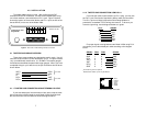
3.0 CONFIGURATION
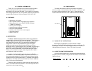
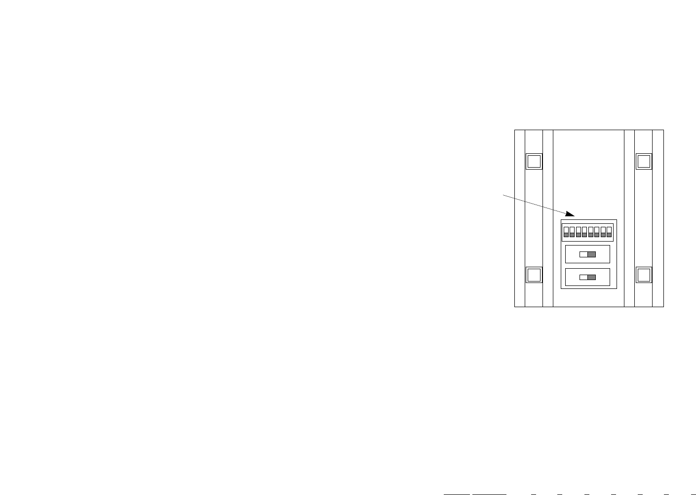
The Model 1060 features externally accessible configuration
switches, located on the underside of the unit; there is no need to open
the case to configure the Model 1060. Figure 1 (below) shows the
location of the DIP switch set, as well as the two DCE/DTE switches.
Figure 1. Switch locations underneath Model 1060
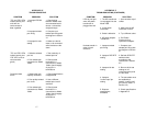
3.1 "QUICK SET-UP" INSTRUCTIONS
In the majority of applications, you won't need an in-depth
knowledge of the Model 1060's capabilities to get up and running. The
following "quick set-up" DIP switch configurations cover most Model
1060 operating environments. (Note: DIP switch 8 not used)
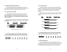
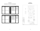
3.1.1 POINT-TO-POINT CONFIGURATION
If you are installing these units in a point-to-point application with a
computer, printer or terminal, configure the DIP switches on both Model
1060s as follows:
Switch Number: 1 2 3 4 5 6 7
Positions OFF OFF OFF ON ON ON OFF
4
E
12345678
ON
DTEDCE
DTEDCE
FRONT
REAR
DIP Switches