


4.1.2 Installing the New QuickConnect™ Module
1) Make sure the power switch on the base unit is off. Leave the
power cord plugged into a grounded outlet to keep the unit
grounded.
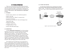
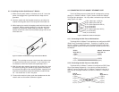
2) Hold the module with the faceplate toward you and align the
module with the guide slots in the rear panel of the base unit.
3) While keeping the module’s faceplate parallel with the base unit
rear panel, slide the module straight in–so that the card edge
contacts line up with the socket inside the chassis. Figure 4
(below) shows how a Quick Connect Module plugs into the rear
of the base unit.
NOTE: The card edge connector should meet the socket when
it is almost all the way into the chassis. If you encounter a lot
of resistance, remove the module and repeat steps 2 & 3.
4) With the card edge contacts aligned with the socket, firmly seat
the module by using your thumbs to apply pressure directly to
the right and left edges of the module faceplate. Applying mod-
erate and
even
pressure should be sufficient to seat the mod-
ule. You should hear it “click” into place.
5) To secure the module in place, push the thumbscrews into the
chassis and turn the screws clockwise to tighten.
9
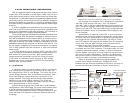
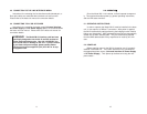
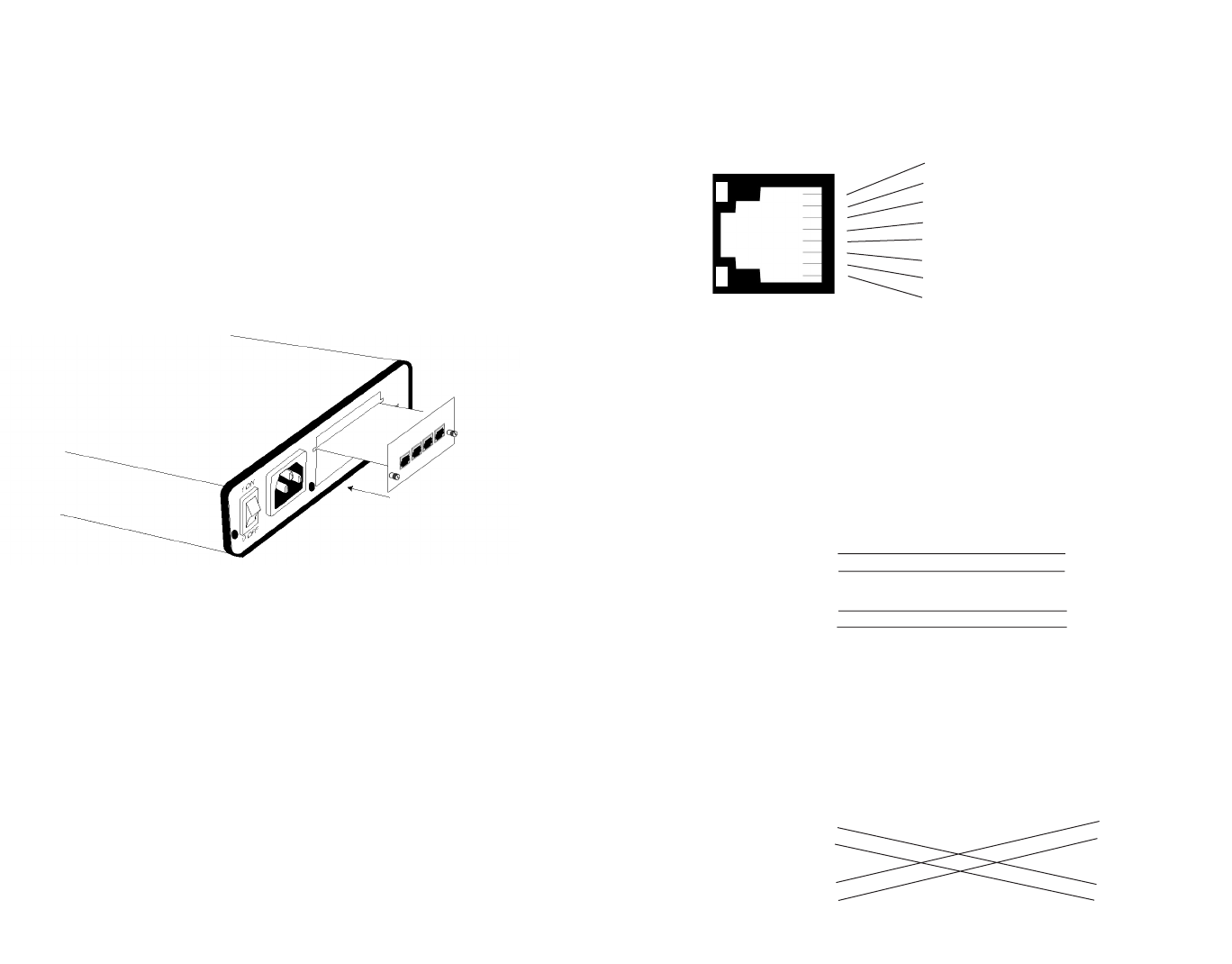
4.2 CONNECTING TO THE 10BASE-T ETHERNET PORT
The RJ-45 Ethernet port on Model IM1/I4 is designed to connect
directly to a 10BaseT network. Figure 5, below, shows the 10BaseT
RJ-45 port pin description. You may make connections up to 330 feet
using Type 4 or 5 cable.
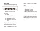
4.2.1 Connecting the Hub Ports to Workstations
The Model IM1/I4 10Base-T hub interfaces are configured as DCE
(Data Circuit Terminating Equipment). Therefore, it “expects” to con-
nect to a 10Base-T workstation using a straight-through RJ-45 cable.
Use the diagram below to construct a cable to connect the IM1/I4 to a
workstation.
IM1/I4 10BaseT Workstation
RJ-45 Pin No. RJ-45 Pin No.
1 (RD+) 1 (TD+)
2 (RD-) 2 (TD-)
3 (TD+) 3 (RD+)
6 (TD-) 6 (RD-)
4.2.2 Connecting the Hub Ports to a Hub (DCE)
The Model IM1/I4 10Base-T interface is configured as DCE (Data
Circuit Terminating Equipment). If you wish to connect the IM1/I4
10Base-T ports to another hub (or a 10Base-T port that “looks like” a
hub), refer to the diagram below to construct a 10Base-T “crossover”
cable.
IM1/I4 Hub
RJ-45 Pin No. RJ-45 Pin No.
1 (RD+) 1 (RD+)
2 (RD-) 2 (RD-)
3 (TD+) 3 (TD+)
6 (TD-) 6 (TD-)
10
Figure 4. Installation of Model IM1/I4 Plug-in Serial Interface Module
1 RD+ (data input to IM1/I4)
2 RD- (data input to IM1/I4)
3 TD+ (data output from IM1/I4)
4 (no connection)
5 (no connection)
6 TD- (data output from IM1/I4)
7 (no connection)
8 (no connection)
1
2
3
4
5
6
7
8
Figure 5. 10BaseT RJ-45 Port Pin Description