


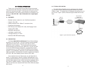

4.3 CONNECTION TO THE LINE INTERFACE MEDIA
Instructions for connecting the line interface media (twisted pair, or
fiber optic cable) are contained within the base unit user manual.
Please refer to the base unit manual for connection details.
4.4 CONNECTING TO AC OR DC POWER
Instructions for connecting the power supply Universal Interface
AC Power Supply and DC Power Supply option) are contained within
the base unit user manual. Please refer to the base unit manual for
connection details.
5.0 OPERATIO
NN
Once the Model IM1/14 is installed, it should operate transparent-
ly. This sections describes power-up, general operating instructions,
and the LED status monitors.
5.1 OPERATING INSTRUCTIONS
In order to operate, the Model IM1/I4 must be installed in the base
unit. It also requires a 10Base-T connection. After power is applied,
the IM1/I4 automatically starts performing the bridging function without
further user intervention. MAC addresses discovered are automatically
loaded into the MAC address table. They are automatically deleted
from the MAC address table if they experience an inactivity of 8 min-
utes.
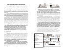
5.2 POWER-UP
Before applying power to the IM1/I4, please be sure it is properly
installed in the base unit. Then make sure that unit is connected to
the appropriate power source (Universal Interface AC Power Supply
or DC Power Supply). Then power-up the base unit using the rear
power switch .
11 12
WARNING! The Model IM1/I4 interface card has been
specifically designed to work with UI and DC versions of
Patton Electronics base units. Use with 120/230VAC ver-
sions could result in damage to the unit. If you are unsure
of your base unit power supply, please contact Patton
Electronics technical support at (301) 975-1007 or at sup-
port@patton.com.