


3.0 CONFIGURATION
The Model 1035 provides sixteen configuration switches, which
allow selection of data rates, clocking methods, V.54 test modes,
RTS/CTS delay and DTE control of test functions. This section
describes switch locations and explains all possible switch
configurations.
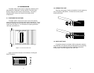
3.1 CONFIGURATION SWITCHES
The Model 1035’s unique set of sixteen internal DIP switches
allows configuration to an extremely wide range of applications. These
switches are grouped into two eight-switch sets and are located on the
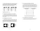
inside of the unit (Figure 1). For instructions on opening the Model
1035 case, see Section 3.2.
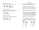
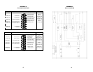
Figure 2 shows the orientation of the switches, including the
ON/OFF positions.
3
Figure 2. Close up of configuration switches
OFF
12345678
DHS-8
OFF
ON
Figure 1. The inside of the Model 1035
OFF
12345678
OFF
12345678
SW1
SW2
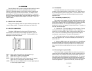
3.2 OPENING THE CASE
Open the unit by gently inserting a screwdriver into the special pry
slot on the plastic case (below). You don't have to worry about
breaking the plastic.
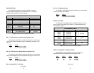
3.3 SWITCH SETTINGS
All possible settings for the Model 1035’s configuration switches
are presented in the summary table and descriptions on the following
pages. If you have additional questions regarding configuration,
contact Patton Technical Support at (301) 975-1007.
4