


5.0 OPERATION
Once the Model 1035 is properly configured and installed, it should
operate transparently—as if it were a standard cable connection.
Section 5.0 describes reading the LED status monitors, powering-up
and using the built-in V.52 and V.54 test modes. The Model 1035 is
powered by a 7.5V DC external wall mount transformer. To power up
the unit, connect the power supply cord to the power jack on the rear of
the Model 1035 and plug the power adapter into the wall. There is no
ON/OFF switch.
5.1 FRONT PANEL SWITCHES
During normal operation, both front panel switches should be in the
“normal” center position. To operate a test mode, see Section 5.3.
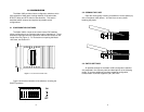
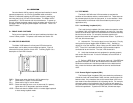
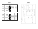
5.2 LED STATUS MONITORS
The Model 1035 features five front panel LEDs that monitor
transmit data, carrier detect, two test modes and power. Figure 6
shows the front panel location of each LED. Following Figure 6 is a
description of each LED’s function.
PWR = Glows green when the Model 1035 is powered up.
TD = Glows red for a “space” on transmit data.
CD = Glows red for high on carrier detect.
BERT = Glows red when bit errors occur in test mode (511 pattern);
Lights when 511/E test pattern has been selected.
LOOP = Glows red when the Model 1035 is in remote digital loopback
or local analog loopback mode.
5.3 TEST MODES
The Model 1035 offers two V.54 test modes to evaluate the
condition of the modems and the communication link. These tests can
be activated physically from the front panel, or via the interface. Note:
V.54 test modes on the Model 1035 are available for point-to-point
applications only.
5.3.1 Local Analog Loopback (LAL)
The Local Analog Loopback (LAL) test checks the operation of the
local Model 1035, and is performed separately on each unit. Any data
sent to the local Model 1035 in this test mode will be echoed (returned)
back to the user device. For example, characters typed on the
keyboard of a terminal will appear on the terminal screen. To perform a
LAL test, follow these steps:
A. Activate LAL. This may be done in one of two ways: First, by
moving the front panel toggle switch DOWN to “LAL”. Second, by
raising pin 18 on the interface. (Note: Make sure DIP switch SW1-8 is
OFF). Once LAL is activated, the Model 1035 transmitter output is
connected to its own receiver. The “test” LED should be lit.
B. Verify that the data terminal equipment is operating properly
and can be used for a test. If a fault is indicated, call a technician or
replace the unit.
C. Perform a BER (bit error rate) test on each unit. If the BER test
equipment indicates no faults, but the data terminal indicates a fault,
follow the manufacturer’s checkout procedures for the data terminal.
Also, check the interface cable between the terminal and the Model
1035.
5.3.2 Remote Digital Loopback (RDL)
The Remote Digital Loopback (RDL) test checks the performance
of both the local and remote Model 1035s, and the communication link
between them. Any characters sent to the remote Model 1035 in this
test mode will be returned back to the originating device. For example,
characters typed on the keyboard of the local terminal will appear on
the local terminal screen after having been passed to the remote Model
1035 and looped back. To perform an RDL test, follow these steps:
(continued)
12
Figure 6. Model 1035’s LED indicators and test switches
TD
CD
PWR BERT LOOP
511/E RDL
NORMAL
511 LAL
11