


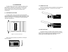
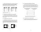
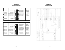

When connecting two Model 1035s, it is necessary to use a twisted
pair “crossover” cable. The diagram below shows how a crossover
cable should be constructed for an environment where both Model
1035s use a 6-wire RJ-11 connector. Similar logic should be followed
when using RJ-45 connectors or a combination of the two.
SIGNAL
PIN# COLOR
‡
COLOR PIN# SIGNAL
GND
†
1 Blue .................White 6 GND
†
RCV 2 Yellow ..............Red 4 XMT
XMT 3 Green...............Black 5 RCV
XMT 4 Red..................Yellow 2 RCV
RCV 5 Black................Green 3 XMT
GND
†
6 White ...............Blue 1 GND
†
†
Connection to ground is optional
‡
Standard color codes—yours may be different
4.2 CONNECTION TO THE RS-232 AND V. 35 INTERFACES
Once you have connected the twisted pair wires correctly, simply
plug the Model 1035 directly into the DB-25 port of the RS-232 or V.35
device. After doing so, remember to insert and tighten the two captive
connector screws.
4.2.1 CONNECTION TO A “DTE” DEVICE
The Model 1035 is wired as a DCE, and therefore “wants” to plug
into a DTE such as a terminal, PC or host. A direct connection to the
RS-232 or V.35 DTE port is most desirable. If you must use a cable to
connect the Model 1035 to the DTE port, make sure it is a
straight
through
cable of the shortest possible length—we recommend 6 feet or
less.
9
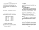
Figure 5. Standard AT&T color codes
1 - Blue
2 - Yellow
3 - Green
4 - Red
5 - Black
6 - White
1 - Blue
2 - Orange
3 - Black
4 - Red
5 - Green
6 - Yellow
7 - Brown
8 - Slate
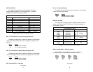
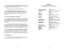
4.2.2 CONNECTION TO AN RS-232 “DCE” DEVICE
Since the Model 1035 is wired as a DCE, you cannot connect it
directly to another DCE such as a modem, multiplexer or printer. If you
need to connect the Model 1035 to another RS-232 DCE device, you
must use a
null modem cable
wired according to diagram below. We
recommend a cable of the shortest possible length, preferably 6 feet or
less.
Connection to Model 1035
†
Connection to DCE Device
DB-25 Pin No. DB-25 Pin No.
1.....................................................1
2.....................................................3
3.....................................................2
4.....................................................8
8.....................................................4
6...................................................20
20.....................................................6
17...................................................24
24...................................................17
7.....................................................7
†
Note: When connected to another DCE device, the Model 1035
should be configured for “external clock” (see Section 3.3).
4.2.3 CONNECTION TO A V.35 “DCE” DEVICE
For details on connecting the Model 1035 to a V.35 DCE, please
contact Patton Electronics Technical Support at (301) 975-1007.
10