


4 RF link Operating Instructions RF link Operating Instructions 13
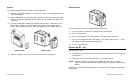
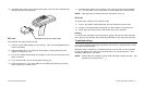
2. Squeeze both sides of the module and snap it into the slots beneath the
terminal (below the keyboard).
PDT 3100
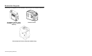
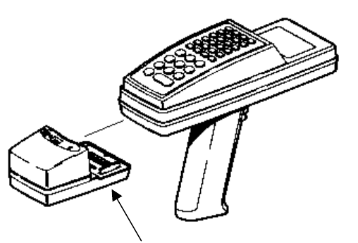
To install RF link onto the PDT 3100:
1. Insert a 9-volt (PP3) battery in the module. See “Inserting Batteries” for
more information.
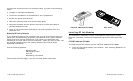
2. Hold the terminal in your hand so the keypad is facing down and the
display is away from you.
3. Pull on the elastic hand strap and unlatch it from the slot just above the
open connector.
4. Turn the terminal over so the keypad is facing up.
5. Hold the module in your other hand so the LEDs are facing up and the
open connector is close to you.
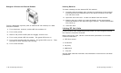
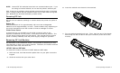
3. Squeeze both sides of the module, and firmly pull the module straight
up. You will hear a loud snap when it comes apart from the terminal.
NOTE: This step may be difficult the first few times you try it.
PDT 3100
To remove the module from the PDT 3100:
1. Pull on the elastic hand strap and remove the latch from the slot.
2. Let go of the hand strap and gently pull the module off the terminal.
3. Latch the hand strap into the slot at the end of the terminal.
Printers
To remove the modules from the printers, gently remove the cable from the
port, and pull the module away from the VELCRO on the side of the printer.
Troubleshooting
If you have problems getting the terminal and printer to communicate via RF
link, follow this flowchart.
Because data is handled in a different manner with an RF unit (as opposed
to using a cable) there may be some differences in processing time. This
situation depends on your data.
NOTE: Internal RF link module's yellow LED indicates a fault occurred. The
symbol next to that LED is:
Squeeze here (and on other side).