


10 of 51
ISSUED: 09-30-09 SHEET #: 056-9024-5 07-18-11
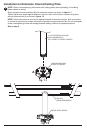
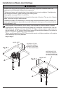
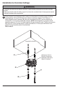
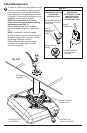
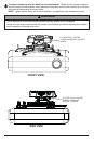
Attach adapter plate (B) to projector using one screw (J, K, L or M) for each channel as shown
below. Tighten all screws, while keeping the center of gravity. Be sure that adapter plate (B) is
straight. Adjust the feet of the channels to keep the adapter plate level. Tighten all screws with
4mm security allen wrench (I) while keeping the center of gravity. If M3 screws (J) are used,
tighten using 2mm security allen wrench (H).
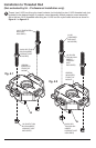
NOTE: Projectors will require different size screws for mounting. Use a combination of screws
(J, K, L or M) and foot adjustment that will result in channels of adapter plate (B) fi tting tightly
against projector. IMPORTANT: In order to properly engage the threads in the mounting holes,
the screw must be turned at least 3 full turns.
NOTE: If using screw (J), place washer (G) between screw (J) and foot of channel.
6
FOOT OF
CHANNEL
J, K, L or M
B
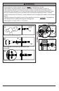
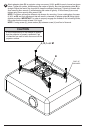
• It is the responsibility of the installer to ensure
that the projector is properly ventilated. Feet
of channels are used to raise the mount off the
projector surface.
CAUTION