


5 of 51
ISSUED: 09-30-09 SHEET #: 056-9024-5 07-18-11
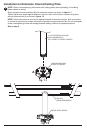
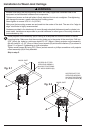
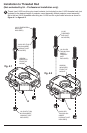
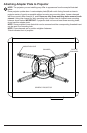
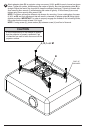
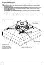
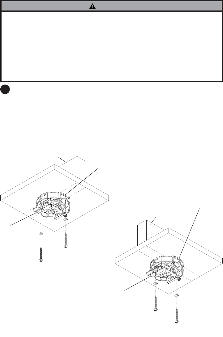
Place projector mount assembly (A) on ceiling as a template and mark the center of the two
mounting holes. Make sure that the mounting holes are in the center of the wood joist. Drill two
5/32" (4mm) dia. holes to a minimum depth of 2-1/2" (64mm). Attach projector mount assembly
(A) with two #14 x 2-1/2" (6mm x 64mm) wood screws (D) and two fl at washers (F) as shown in
fi gure 2.1 or fi gure 2.2 depending on joist orientation.
Tighten wood screws (D) using 3/8" (10mm) socket wrench or phillips screwdriver until projector
mount assembly (A) is fi rmly attached.
Skip to step 5.
2
Installation to Wood Joist Ceilings
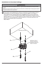
• Installer must verify that the supporting surface will safely support the combined load of the
equipment and all attached hardware and components.
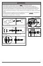
• Tighten wood screws so that wall plate is fi rmly attached, but do not overtighten. Overtightening
can damage the screws, greatly reducing their holding power.
• Never tighten in excess of 80 in. • lb (9 N.M.).
• Make sure that mounting screws are anchored into the center of the stud. The use of an "edge to
edge" stud fi nder is highly recommended.
• Hardware provided is for attachment of mount through standard thickness drywall or plaster into
wood studs. Installers are responsible to provide hardware for other types of mounting situations
(not evaluated ny UL).
WARNING
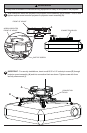
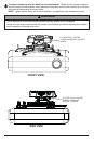
D
D
A
WOOD JOIST
F
F
WOOD JOIST
A
ACCESS SLOT FOR
OPEN END WRENCH
ALLOWS TIGHTENING
OF WOOD SCREW (D).
ACCESS SLOT FOR
OPEN END WRENCH
ALLOWS TIGHTENING
OF WOOD SCREW (D).
fi g. 2.1
fi g. 2.2