


6 of 51
ISSUED: 09-30-09 SHEET #: 056-9024-5 07-18-11
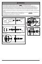
• Concrete must be 2000 psi density minimum. Lighter density concrete may not hold concrete
anchor.
• Make sure that the wall will safely support four times the combined load of the equipment and all
attached hardware and components.
WARNING
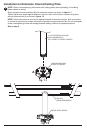
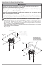
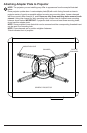
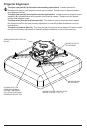
Place projector mount assembly (A) on ceiling as a template and mark the center of the two
mounting holes. Drill two 5/16" (8mm) dia. holes to a minimum depth of 2-1/2" (64mm).
Attach projector mount assembly (A) using two concrete anchors (C), two fl at washers (F),
and two #14 x 2-1/2" wood screws (D) as shown. NOTE: Mounting slots on projector mount
assembly allow for 30° (±15°) of rotation before fully securing wood screw. Tighten wood screws
(D) using 3/8" (10mm) socket wrench, phillips screwdriver or 10mm open end wrench until
projector mount assembly (A) is fi rmly attached.
Skip to step 5.
3
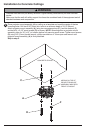
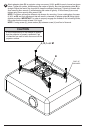
Installation to Concrete Ceilings
D
A
CONCRETE CEILING
F
C
ARROW ON TOP OF
PROJECTOR MOUNT
ASSEMBLY INDICATES
FRONT OF MOUNT