


C1572M (9/05) 83
FRONT VIEW
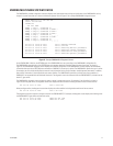
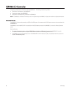
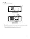
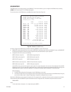
Figure 38 illustrates the front of the CM9700-CC1.
Figure 38. CM9700-CC1 Front View
Note the following:
• The door of the CM9700-CC1 is secured by a Phillips-head screw on the knob. To open the door, loosen the screw on the knob.
• In addition to the AT-compatible keyboard port on the front of the CM9700-CC1, another AT-compatible keyboard port is located on the rear
of the unit. Both keyboard ports cannot be used at the same time.
• The power LED lights green to indicate that AC power is being applied to the unit.
• Because of the solid state flash memory of the CM9700-CC1, the hard disk drive LED is not used.
MOUNTING HANDLES
DOOR
CM9700-CC1 FRONT VIEW WITH DOOR CLOSED
CM9700-CC1 FRONT VIEW WITH DOOR OPEN
KEYBOARD
PORT
POWER
LED
FLOPPY DISK DRIVE
RESET
BUTTON
HARD DISK
DRIVE LED
(NOT USED)
KNOB