


2 Pelco Manual C930M-E (12/95)
4.0 SPECIFICATIONS
ELECTRICAL
Connectors:
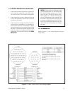
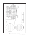
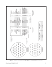
Receiver side CPC, 37 sockets
Pan/tilt side CPC, 14 pins
CPC, 28 pins (PP models)
Cable: 12 conductor with shield, 20 Awg
RG59/U
GENERAL
Cable length:
C1906 6 ft (1.83 m) long
C1925 25 ft (7.62 m) long
C19125 125 ft (38.1 m) long
C1906/PP 6 ft (1.83 m) long
C1925/PP 25 ft (7.62 m) long
Maximum Wire
Temperature: 140° F (60° C)
5.0 INSTALLATION
1. Run the cable from the Coaxitron
®
receiver/driver
to the pan/tilt. Be careful not to abrade or cut the
jacket on the cable since this could result in a short.
2. Connect the 37-pin CPC connector to the
Coaxitron
®
receiver/driver.
3. Connect the 14-socket CPC connector (28-pin PP
models) to the pan/tilt unit.
4. Operate the control unit and determine correct op-
eration of the unit. If the unit fails to operate cor-
rectly, refer to the troubleshooting guidelines out-
lined in Section 7.0.
6.0 OPERATION
By using the controller, you should be able to control
the pan and tilt functions of the pan/tilt and the focus,
iris, and zoom functions of the motor operated lens.
6.1 SYSTEM TEST
Using the controller, operate the following functions
and verify correct operation of each function:
1. Pan Left
2. Pan Right
3. Tilt Up
4. Tilt Down
5. Zoom Wide
6. Zoom Telephoto
7. Iris Open
8. Iris Closed
9. Focus Near
10. Focus Far
If all the above functions operate correctly, the instal-
lation process is complete. If all the above functions do
not operate correctly, refer to Section 7.0, Troubleshoot-
ing Guidelines.
For PP models — check all of the above again
using a set preset location.