


Pelco Manual C930M-E (12/95) 3
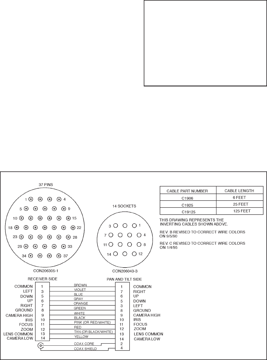
NOTE: These cables are designed for use
in inverted applications. If you wish to modify
the cable for upright operation, pins 3 and 7
(pan) and pins 5 and 6 (tilt) need to be re-
versed on the 14- or 28-pin connector (pan/
tilt side). The problem can be corrected in the
field with a CPC pin/socket extracting tool
by simply exchanging the pins for these func-
tions. If you do not have the necessary tool,
contact Pelco for a R/A number to exchange
the cable.
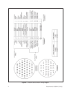
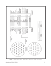
8.0 SCHEMATICS
Refer to Figures 1-3 for wiring diagrams of the pre-
wired cables.
Figure 1. C1906, C1925, and C19125 Wiring Diagram
7.0 TROUBLESHOOTING GUIDELINES
1. If none of the functions in Section 6.1 operate cor-
rectly, check the connection of the CPC connec-
tors to the Coaxitron
®
receiver/driver and pan/tilt.
2. If the connections are loose, tighten the lock ring
on the CPC connectors and start the system test
procedure in Section 6.1.
3. If the connections are tight, check the Coaxitron
®
receiver/driver to determine if it is operating cor-
rectly. If the Coaxitron
®
receiver/driver is operat-
ing correctly, there may be a problem with the cable
and Pelco’s Technical Assistance Program (TAP)
should be contacted for further technical trouble-
shooting aid. To contact the TAP line, call 1-800-
289-9100.