


Perle Gigabit Fiber to Fiber Media Installation Guide
6
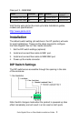
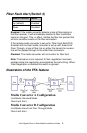
Sequence of Events
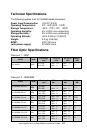
1. Media Converter
A
loses fiber connection (RX) on MM2/SM2.
2. Media Converter
A
disables the transmitter (TX) MM2/SM2.
3. Media Converter
B
detects loss of fiber link on receiver RX –
MM2/SM2.
4. Media Converter
B
turns off transmitter (TX) on MM1.
5. Media Converter
A
MM1 is not affected
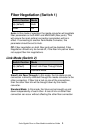
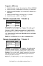
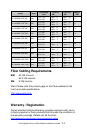
Remote Loopback Fiber 1 (Switch 4)
Switch Position
Mode
Up (default) Disabled
Down Enabled
Disabled: The loopback feature is disabled. This is the normal
position for regular operation. The switch must be set to this
position in order for data to pass through the media converter.
Enabled: This is a test mode. All data received on the receive
(RX) fiber connection on port MM1 is looped back to the transmit
(TX) fiber connection.
Note: Only one fiber interface can be in loopback at a time.
Remote Loopback Fiber 2 (Switch 5)
Switch Position
Mode
Up (default) Disabled
Down Enabled
Disabled: The loopback feature is disabled. This is the normal
position for regular operation. The switch must be set to this
position in order for data to pass through the media converter.
Enabled: This is a test mode. All data received on the receive
(RX) fiber connection on port MM/SM2 is looped back to the
transmit (TX) fiber connection.
Note: Only one fiber interface can be in loopback at a time.