


Philips Semiconductors Product specification
TOPFET high side switch BUK205-50Y
SMD version of BUK201-50Y
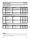
STATIC CHARACTERISTICS
T
mb
= 25 ˚C unless otherwise stated
SYMBOL PARAMETER CONDITIONS MIN. TYP. MAX. UNIT
Clamping voltages
V
BG
Battery to ground I
G
= 1 mA 50 55 65 V
V
BL
Battery to load I
L
= I
G
= 1 mA 50 55 65 V
-V
LG
Negative load to ground I
L
= 1 mA 12 17 21 V
Supply voltage battery to ground
V
BG
Operating range
1
-5-40V
Currents V
BG
= 13 V
I
L
Nominal load current
2
V
BL
= 0.5 V; T
mb
= 85 ˚C 6 - - A
I
B
Quiescent current
3
V
IG
= 0 V; V
LG
= 0 V - 0.1 2 µA
I
G
Operating current
4
V
IG
= 5 V; I
L
= 0 A 1.5 2.2 4 mA
I
L
Off-state load current
5
V
BL
= 13 V; V
IG
= 0 V - 0.1 1 µA
Resistances
R
ON
On-state resistance
6
V
BG
= 13 V; I
L
= 7.5 A; t
p
= 300 µs - 45 60 mΩ
R
ON
On-state resistance V
BG
= 5 V; I
L
= 1.5 A; t
p
= 300 µs - 70 90 mΩ
R
G
Internal ground resistance I
G
= 10 mA - 150 - Ω
INPUT CHARACTERISTICS
T
mb
= 25 ˚C; V
BG
= 13 V
SYMBOL PARAMETER CONDITIONS MIN. TYP. MAX. UNIT
I
I
Input current V
IG
= 5 V 35 60 100 µA
V
IG
Input clamping voltage I
I
= 200 µA 6 7.5 8.5 V
V
IG(ON)
Input turn-on threshold voltage - 2.1 2.7 V
V
IG(OFF)
Input turn-off threshold voltage 1.5 2 - V
1 On-state resistance is increased if the supply voltage is less than 9 V. Refer to figure 8.
2 Defined as in ISO 10483-1.
3 This is the continuous current drawn from the battery when the input is low and includes leakage current to the load.
4 This is the continuous current drawn from the battery with no load connected, but with the input high.
5 The measured current is in the load pin only.
6 The supply and input voltage for the R
ON
tests are continuous. The specified pulse duration t
p
refers only to the applied load current.
July 1996 3 Rev 1.000