


Philips Semiconductors Product specification
TOPFET high side switch BUK205-50Y
SMD version of BUK201-50Y
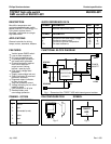
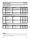
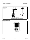
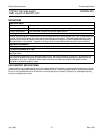
Fig.4. High side switch measurements schematic.
(current and voltage conventions)
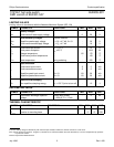
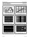
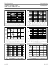
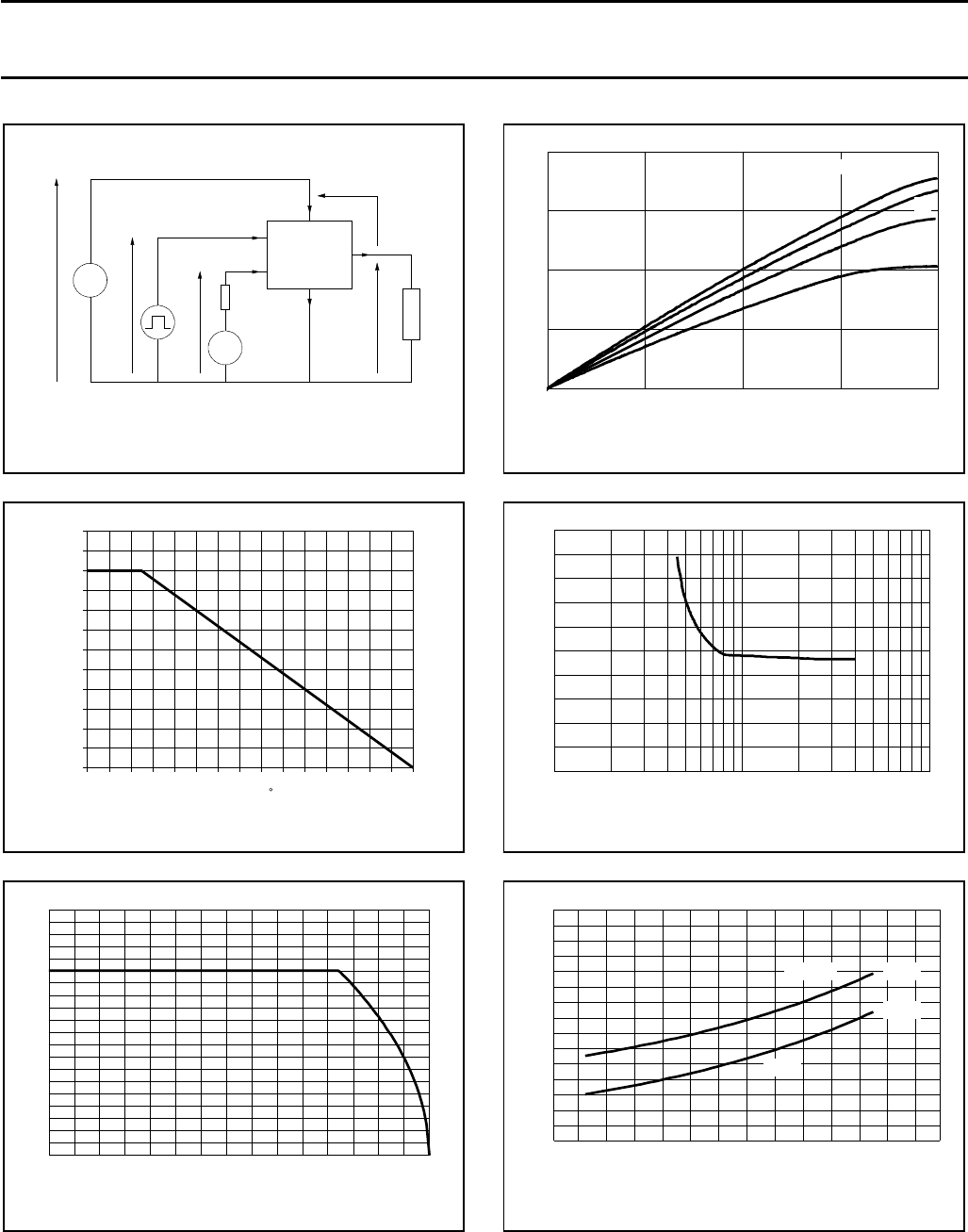
Fig.5. Normalised limiting power dissipation.
P
D
% = 100
⋅
P
D
/P
D
(25 ˚C) = f(T
mb
)
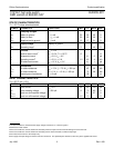
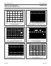
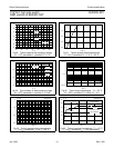
Fig.6. Limiting continuous on-state load current.
I
L
= f(T
mb
); conditions: V
IG
= 5 V, V
BG
= 13 V
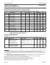
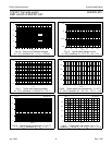
Fig.7. Typical on-state characteristics, T
j
= 25 ˚C.
I
L
= f(V
BL
); parameter V
BG
; t
p
= 250
µ
s
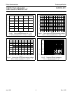
Fig.8. Typical on-state resistance, T
j
= 25 ˚C.
R
ON
= f(V
BG
); conditions: I
L
= 7.5 A; t
p
= 300
µ
s
Fig.9. Typical on-state resistance, t
p
= 300
µ
s.
R
ON
= f(T
j
); parameter V
BG
; condition I
L
= 1.5 A
L
I
S
TOPFET
HSS
B
G
IB
IG
II
IS
IL
VBG
VIG
VSG
RS
VLG
LOAD
VBL
0 0.5 1 1.5 2
0
10
20
30
40
BUK205-50Y
VBL / V
IL / A
6
7
13
5
VBG / V =
0 20 40 60 80 100 120 140
Tmb / C
PD%
Normalised Power Derating
120
110
100
90
80
70
60
50
40
30
20
10
0
1 10 100
0
10
20
30
40
50
60
70
80
90
100
BUK205-50Y
VBG / V
RON / mOhm
0 50 100 150
0
5
10
15
20
BUK205-50Y
Tmb / C
IL / A
BUK205-50Y
Tmb / C
-60 -20 20 60 100 140 180
RON / mOhm
0
50
100
150
VBG =
5 V
13 V
typ.
July 1996 6 Rev 1.000