


Philips Semiconductors Product specification
TOPFET high side switch BUK205-50Y
SMD version of BUK201-50Y
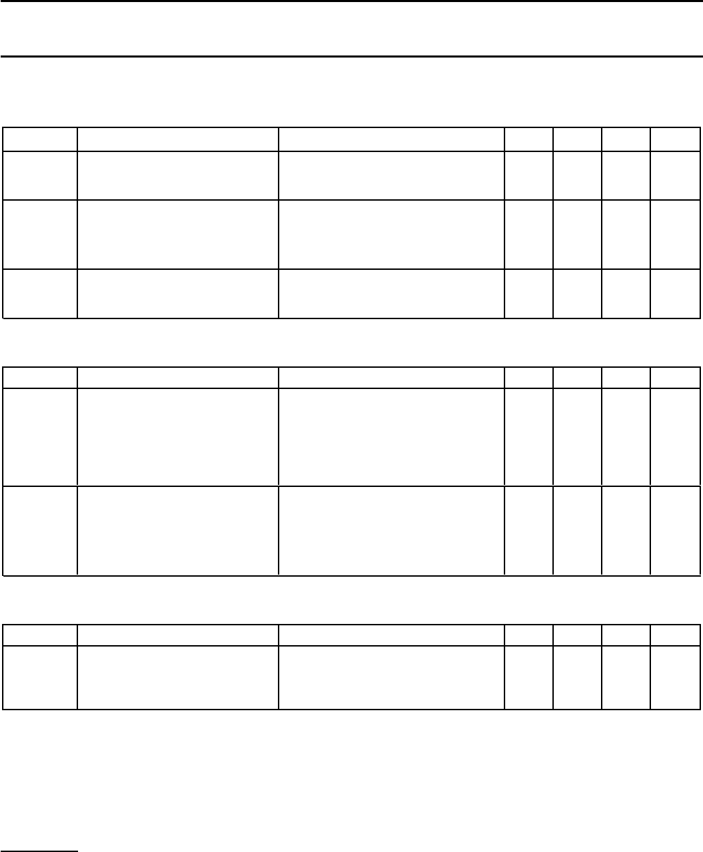
DYNAMIC CHARACTERISTICS
T
mb
= 25 ˚C; V
BG
= 13 V
SYMBOL PARAMETER CONDITIONS MIN. TYP. MAX. UNIT
Inductive load turn-off
-V
LG
Negative load voltage
1
V
IG
= 0 V; I
L
= 7.5 A; t
p
= 300 µs152025V
Short circuit load protection
2
V
IG
= 5 V; R
L
≤ 10 mΩ
t
d sc
Response time - 90 - µs
I
L
Load current prior to turn-off t < t
d sc
-42- A
Overload protection
3
I
L(lim)
Load current limiting V
BL
= 9 V; t
p
= 300 µs284052A
SWITCHING CHARACTERISTICS
T
mb
= 25 ˚C, V
BG
= 13 V, for resistive load R
L
= 13 Ω.
SYMBOL PARAMETER CONDITIONS MIN. TYP. MAX. UNIT
During turn-on to V
IG
= 5 V
t
d on
Delay time to 10% V
L
-16-µs
dV/dt
on
Rate of rise of load voltage - 1 2.5 V/µs
t
on
Total switching time to 90% V
L
-40-µs
During turn-off to V
IG
= 0 V
t
d off
Delay time to 90% V
L
-30-µs
dV/dt
off
Rate of fall of load voltage - 1.2 2.5 V/µs
t
off
Total switching time to 10% V
L
-50-µs
CAPACITANCES
T
mb
= 25 ˚C; f = 1 MHz; V
IG
= 0 V
SYMBOL PARAMETER CONDITIONS MIN. TYP. MAX. UNIT
C
ig
Input capacitance V
BG
= 13 V - 15 20 pF
C
bl
Output capacitance V
BL
= V
BG
= 13 V - 415 580 pF
C
sg
Status capacitance V
SG
= 5 V - 11 15 pF
1 For a high side switch, the load pin voltage goes negative with respect to ground during the turn-off of an inductive load. This negative voltage
is clamped by the device.
2 The load current is self-limited during the response time for short circuit load protection. Response time is measured from when input goes
high.
3 If the load resistance is low, but not a complete short circuit, such that the on-state voltage remains less than V
BL(TO)
, the device remains in
current limiting until the overtemperature protection operates.
July 1996 5 Rev 1.000