


1999 May 31 7
Philips Semiconductors Product specification
Home automation modem TDA5051A
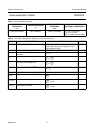
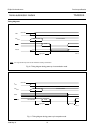
t
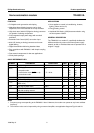
W(DI)(min)
minimum pulse width of
DATA
IN
signal
f
osc
= 8.48 MHz;
see Fig.8
− 190 −µs
V
o(rms)
output carrier signal
(RMS value)
Z
L
= CISPR16;
DATA
IN
= LOW
120 − 122 dBµV
I
o(max)
power amplifier maximum
output current (peak value)
Z
L
=1Ω;
DATA
IN
= LOW
− 160 − mA
Z
o
output impedance of the
power amplifier
− 5 −Ω
V
O
output DC level at
pin TX
OUT
− 2.5 − V
THD total harmonic distortion on
CISPR16 load with the
coupling network
(measured on the first ten
harmonics)
V
o(rms)
= 121 dBµV on
CISPR16 load;
f
osc
= 8.48 MHz;
DATA
IN
= LOW
(no modulation);
see Figs 3 and 16
−−55 − dB
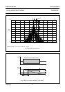
B
−20dB
bandwidth of the shaped
output signal (at −20 dB)
on CISPR16 load with the
coupling network
V
o(rms)
= 121 dBµV on
CISPR16 load;
f
osc
= 8.48 MHz;
DATA
IN
= 300 Hz;
duty factor = 50%;
see Fig.4
− 3000 − Hz
Reception mode
V
i(rms)
analog input signal
(RMS value)
82 − 122 dBµV
V
I
DC level at pin RX
IN
− 2.5 − V
Z
i
RX
IN
input impedance − 50 − kΩ
R
AGC
AGC range − 36 − dB
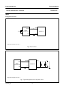
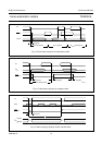
t
c(AGC)
AGC time constant f
osc
= 8.48 MHz;
see Fig.5
− 296 −µs
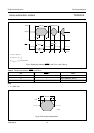
t
d(dem)(su)
demodulation delay set-up
time
f
osc
= 8.48 MHz;
see Fig.15
− 350 400 µs
t
d(dem)(h)
demodulation delay hold
time
f
osc
= 8.48 MHz;
see Fig.15
− 420 470 µs
B
det
detection bandwidth f
osc
= 8.48 MHz − 3 − kHz
BER bit error rate f
osc
= 8.48 MHz;
600 baud; S/N = 35 dB;
signal 76 dBµV;
see Fig.17
− 1 − 1 × 10
−4
SYMBOL PARAMETER CONDITIONS MIN. TYP. MAX. UNIT