


Title: Product Specification: LC12 High-Bright Monitor Page 10 of 24
Document Number: 023-0284-01 Revision: A
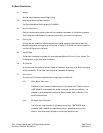
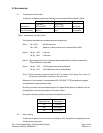
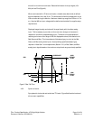
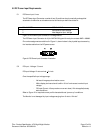
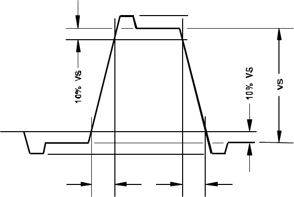
where 0-mv is minimum luminance. Rise and fall times for the input signal (10% -
90%) will be ?5-ns (Figure 6).
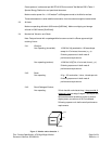
When terminated with a 75-ohm termination, the dark state (black level) is defined
as a level between 0-mv and 10-mv. The white state (full white) is dependent on the
VGA controller driving the Monitor. Maximum levels may range from 550-mv to 714-
mv. Nominal 680-mv input voltage shall be defined as the default for supplier setup
requirements.
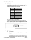
Displayed image intensity and colors will change linearly with the video analog
input. This is necessary to provide a uniform user color change on the screen in
response to a uniformly stepped analog input. The Monitor must be capable of
resolving a minimum color range of 262,144 displayable colors (6 bit resolution for
Red, Green and Blue). This interpolates to 64 shades of gray (or color) at the Red,
Green, and Blue analog video inputs. Accomplishing specified shades of gray
requires a “Video Gain” control adjustment (Section 15.0 ) of Red, Green, and Blue
analog input signals based on the maximum output level range previously specified.
RISE
TIME
FALL
TIME
NEG
POS
HIGH
STEADY
LEVEL
LOW
STEADY
LEVEL
OVERSHOOT
Figure 5. Rise / Fall Time
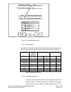
4.2.2 Synchronization
Sync pulses for horizontal and vertical are TTL levels. Figure 8 defines the levels and
drive current capabilities.