


Title: Product Specification: LC12 High-Bright Monitor Page 15 of 24
Document Number: 023-0284-01 Revision: A
5.0 DC Power Input Requirements
5.1 DC Power Input Lines
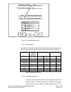
The DC Power Input Connector consists of two (2) positions wired numerically and supplied
attached to the Monitor as a chassis mounted connector per definitions listed in.
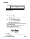
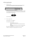
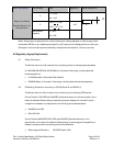
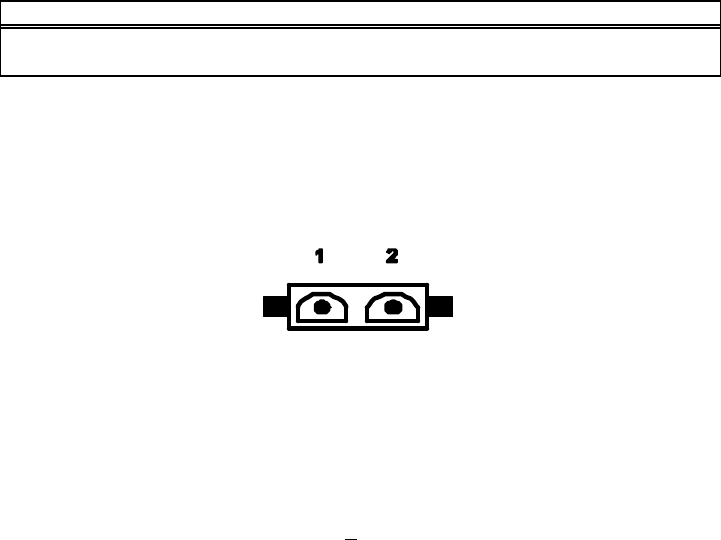
PIN NUMBER SIGNAL NAME
1 Most Positive Input Voltage
2 Most Negative Input Voltage
Figure 10. DC Power Input Connector- Pin Assignments
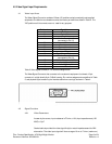
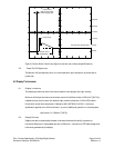
The DC Power Input Connector is a 2 pin MAT-N-LOK type with male pin contacts AMP 1 480699.
Pin number assignments are defined in Figure 11; shown below is the physical layout as seen by
the interface cable from the DC power source.
Figure 8. DC Power Input Connector Illustration
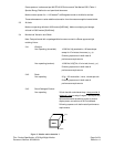
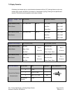
5.2 DC Input Voltage / Current
DC Input Voltage: 12 vdc nominal, + 0.4 vdc.
Over the specified input voltage range:
- No loss of image synchronization occurs.
- White display luminance level is within 10% of luminance at nominal input
voltage.
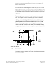
- DC Input Current: 4.3 amp maximum current draw (12.4-vdc applied) steady
state conditions.
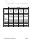
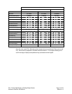
Refer to Figure 12 for required current profile characteristics at “power–up” conditions.
The Monitor is not damaged by input voltages ranging from 0-vdc to 12.4-vdc".