


Title: Product Specification: LC12 High-Bright Monitor Page 9 of 24
Document Number: 023-0284-01 Revision: A
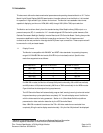
4.0 Video Signal Input Requirements
4.1 Video Input Lines
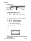
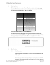
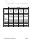
The Video Signal Connector consists of fifteen (15) positions wired numerically and supplied
attached to the Monitor as a chassis mounted connector per definitions listed in Table 2. The
"NC" positions of this connector are not used for any purpose.
Pin Number Signal Name
1 Red Video
2 Green Video
3 Blue Video
4 Monitor Sense Line 3
(connected to Pin 10)
5 NC
6 Red video return
7 Green video return
8 Blue video return
9 NC
10 Signal Ground Reference
11 Monitor Sense Line 1
(connected to Pin 10)
12 Monitor Sense Line 2 (NC)
13 Horizontal Sync Input
14 Vertical Sync Input
15 NC
Table 2. Video Signal Connector – Pin Number Assignments
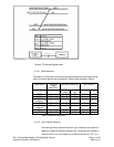
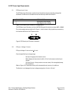
The Video Signal Connector that connects to the customer’s equipment is a female 15-pin
connector in a high density 9-pin D-Shell housing. Pin number assignments are defined in Table
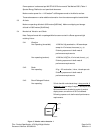
2, and physical layout as seen by the interface cable from user logic is shown in Table 4.
Figure 4. Video Signal Connector Illustration
4.2 Signal Functions
4.2.1 Video Parameters
As seen by the source, input resistance is 75-ohm, ±10%; input capacitance at (150
MHZ) <10-pF.
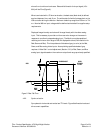
Coaxial cable is provided for video signal line(s) to match impedances and for EMI
attenuation. The video input signal will have a range of 0-mv to 714-mv (maximum)