


- 66 -
7. THE POE PROVISION PROCESS
While adding PoE support to networked devices is relatively painless, it should be realized that power cannot simply be
transferred over existing CAT-5 cables. Without proper preparation, doing so may result in damage to devices that are not
designed to support provision of power over their network interfaces.
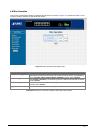
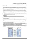
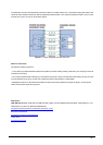
The PSE is the manager of the PoE process. In the beginning, only small voltage level is induced on the port's output, till a
valid PD is detected during the Detection period. The PSE may choose to perform classification, to estimate the amount of
power to be consumed by this PD. After a time-controlled start-up, the PSE begins supplying the 48 VDC level to the PD, till
it is physically or electrically disconnected. Upon disconnection, voltage and power shut down.
Since the PSE is responsible for the PoE process timing, it is the one generating the probing signals prior to operating the
PD and monitoring the various scenarios that may occur during operation.
All probing is done using voltage induction and current measurement in return.
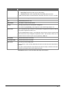
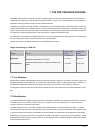
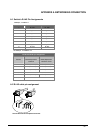
Stages of powering up a PoE link
Stage Action
Volts speci-
fied
per 802.3af
Volts man-
aged
by chipset
Detection
Measure whether powered device has the correct
signature resistance of 15–33 kΩ
2.7-10.0 1.8–10.0
Classification
Measure which power level class the resistor indi-
cates
14.5-20.5 12.5–25.0
Startup
Where the powered device will startup >42 >38
Normal operation
Supply power to device 36-57 25.0–60.0
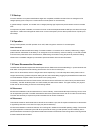
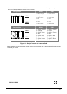
7.1 Line Detection
Before power is applied, safety dictates that it must first be ensured that a valid PD is connected to the PSE's output. This
and involves the PSE seeking a specific, 25 KΩ signature resistor. Detection of
is signature indicates that a valid PD is connected, and that provision of power to the device may commence.
he signature resistor lies in the PD's PoE front-end, isolated from the rest of the the PD's circuitries till detection is certi-
ed.
ation, to determine the maximal power a PD is to consume.
.5 VDC, limited to 100 mA, for a period of 10 to 75 ms responded by a certain current con-
class.
igned to one of 5 classes: 0 (default class) indicates that full 15.4 watts should be provided, 1-3 indicate
levels and 4 is reserved for future use. PDs that do not support classification are assigned to class
0. Special care must be employed in the definition of class thresholds, as classification may be affected by cable losses.
Classifying a PD according to its power consumption may assist a PoE system in optimizing its power distribution. Such a
system typically suffers from lack of power resources, so that efficient power management based on classification results
may reduce total system costs.
process is referred to as "line detection",
th
T
fi
7.2 Classification
Once a PD is detected, the PSE may optionally perform classific
The PSE induces 15.5-20
sumption by the PD, indicating its power
The PD is ass
various required power