


F-23371 Electronic Speed Switch Technical Manual Page 1
2002 Invensys. All Rights Reserved
1.0 INTRODUCTION
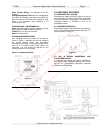
The Barber-Colman two setpoint speed switch
normally obtains its input signal from a magnetic
pickup which is positioned in proximity to the teeth of
a gear on a rotating shaft. The pickup generates an
AC signal voltage whose frequency is directly
proportional to the rate at which the gear teeth pass
by the pole piece. The speed switch converts the
input signal voltage into a DC signal which is
compared to the preset levels (setpoints) and actuate
the relays when the input signal frequency exceeds
the preset values.
1.1 APPLICATION
l Overspeed Protection Signal
l Underspeed Protection Signal
l Crank Termination Signal
l Generator Field Flashing Signal
l Ignition Signal
l Sequencing Signal
l Tach Signal for Driving Model 40 Tachometer
1.2 RELAY LOGIC TABLE FOR SPEED SWITCHES
Switch
Power to Unit
and Input Signal
Frequency
below Trip Point
Power to Unit and
Input Signal
Frequency above Trip
Point
DYNZ-60010
SWl Relay
Contacts
De-energized
10 to 12 closed
11 to 12 open
Energized (non-
latching)
10 to 12 open
11 to 12 closed
DYNZ-60010
OS-SW2
Relay
Contacts
Energized
7 to 9 open
8 to 9 closed
De-energized (latched)
7 to 9 closed
8 to 9 open
DYNZ-60012
SW1 Relay
Contacts
De-energized
10 to 12 closed
11 to 12 open
Energized (non-
latching)
10 to 12 open
11 to 12 closed
DYNZ-60012
OS-SW2
Relay
Contacts
De-energized
7 to 9 closed
8 to 9 open
Energized (non-
latching)
7 to 9 open
8 to 9 closed
DYNZ-60013
SW1 Relay
Contacts
De-energized
10 to 12 closed
11 to 12 open
Energized (non-
latching)
10 to 12 open
11 to 12 closed
DYNZ-60013
OS-SW2
Relay
Contacts
De-energized
7 to 9 closed
8 to 9 open
Energized (non-
latching)
7 to 9 open
8 to 9 closed
2.0 SPECIFICATIONS
2.1 ELECTRICAL
2.1.1 COMMON ELECTRICAL SPECIFICATIONS
FOR DYNZ-60010, DYNZ-60012 AND DYNZ-60013
Ambient Operating Temperature: -40 to +185°F (-
40 to +85°C).
Maximum Operating Current: 0.20 amperes.
Input Signal Voltage: 0 7 Vrms minimum into 33 k
ohm load.
Trip Setpoint: Adjustable 325 to 10,000 Hz.
SW1: Factory set at 1100 Hz.
SW2: Factory set at 3600 Hz.
Repeatability: ±5 Hz or ±1%, whichever is greater.
2.1.2 ELECTRICAL SPECIFICATIONS FOR DYNZ-
60010
Power Input: 8 to 40 Vdc.
Voltage Transients: Withstand 200 volts forward and
reverse peaks of 10 milliseconds duration at 5 ohms
source input impedance. Withstand 80 volts forward
and reverse peaks of 50 milliseconds duration at 50
ohms source input impedance.
Hysteresis:
SW1: Crank dropout, non-latching; nominal 165 Hz
SW2: Overspeed, latching; 100% of setpoint.
Relay Contact Rating: 10 amperes at 30 Vdc
resistive.
Overspeed Response Time: With the overspeed set
at 4140 Hz and a steady input frequency of 3600 Hz,
then switching the input frequency to 5000 Hz must
result in the overspeed relay operating in 90
milliseconds or less.
2.1.3 ELECTRICAL SPECIFICATIONS FOR DYNZ-
60012
Power Input: 59 to 88 Vdc.
Voltage Transients: Withstand 200 volts forward and
reverse peaks of 10 milliseconds duration at 50 ohms
source input impedance. Withstand 80 volts forward
and reverse peaks of 50 milliseconds duration at 50
ohms source input impedance.
Hysteresis:
SW1: Crank dropout, non-latching; nominal 165 Hz
SW2: Overspeed, non-latching; 0% of setpoint.
Relay Contact Rating: 0.75 amperes at 88 Vdc
resistive.
Overspeed Response Time: With the overspeed set
at 4140 Hz and a steady input frequency of 3600 Hz,
then switching the input frequency to 5000 Hz must
result in the overspeed relay operating in 75
milliseconds or less.
2.1.4 ELECTRICAL SPECIFICATIONS FOR DYNZ-
60013
Power Input: 8 to 40 Vdc.
Voltage Transients: Withstand 200 volts forward and
reverse peaks of 10 milliseconds duration at 50 ohms
source input impedance. Withstand 80 volts forward
and reverse peaks of 50 milliseconds duration at 50
ohms source input impedance.
Hysteresis:
SW1: Crank dropout, non-latching; nominal 165 Hz
SW2: Overspeed, non-latching; 0% of setpoint.
Note
Barber-
Colman believes that all information provided
herein is correct and reliable and reserves the right to
update at any time. Barber0Colman does not assume
any responsibility for its use unless otherwise expr
essly
undertaken.
Caution
As a safety measure, Barber-
Colman Company
recommends that all engines and turbines be equipped
with an independent overspeed shutdown devise.
Uncontrolled Document
For Historical Reference Only