


F-23371 Electronic Speed Switch Technical Manual Page 3
2002 Invensys. All Rights Reserved
l Barber-Colman sets the units to operate over the
adjustment range of 325 to 10,000 Hz by cutting
jumper J2 only. The sensitivity of the adjustment
potentiometer is approximately 480 Hz per turn.
n SW1 is factory set at 1100 Hz unless specified in
purchase order.
n OS-SW2 is factory set at 3600 Hz unless specified
in purchase order.
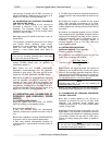
l The unit can be operated at a lower frequency
adjustment range (80 to 2500 Hz instead of 325 to
10,000 Hz) by reconnecting jumper J2 and cutting out
jumper J1 (see Figure 2).
4.0 WIRING INSTRUCTIONS
The typical wiring diagram shows the wiring required
to properly connect the unit to the DYNA governor. All
the wiring for the test, tach and input power terminals
should be either 18 or 20 AWG wire. The wiring to the
relay contacts should be 16 AWG wire if the current
requirement is less than 5 amperes and 14
AWG if the current through the contacts is between 5
and 10 amperes. The current load and wiring to the
relay should be checked thoroughly.
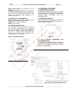
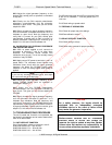
As shown in Figure 3, a two-conductor shielded cable
must be used for mounting the speed sensor (MPU)
to the unit. The shield should only be connected as
shown. It is good practice to isolate the power wiring
from the relay contacts and associated relays from
the input signal wiring. The input signal is normally
from a magnetic pickup (MPU) mounted on the
flywheel housing which senses the ring gear speed.
5.0 OPERATION AND CALIBRATION OF
DYNZ-60010
SPEED SWITCH
5.1 OPERATING PROCEDURE
Once the system has been wired, the SPEED
SWITCH functions in the following manner.
5.1.1 No power applied to unit.
l SW1 and OS-SW2 relays are de-energized;
therefore, contacts are in position as shown on top of
unit.
5.1.2 Power is applied to unit when POWER SWITCH
is turned on and no input signal to speed switch.
l SW1 relay remains de-energized; therefore, its
contacts remain in same position as those shown on
top of unit.
l OS-SW2 relay energizes; therefore, its contacts
change states from those shown on top of unit.
5.1.3 When the engine is cranked and the engine
starts, SW1 energizes at its crank-dropout setting
which is normally adjusted midway between the
cranking RPM and idle RPM of the engine.
5.1.4 When an overspeed condition occurs, OS-SW2
relay deenergizes and latches up and will remain
latched up until the POWER SWITCH is turned off or
power is somehow removed from the unit. The engine
overspeed setpoint is normally adjusted to trip at 10 to
20% above the engine operating speed.
5.2 CALIBRATION PROCEDURE
Equipment Required: Signal generator
Frequency counter Ohmmeter
5.2.1 Determine the desired trip points for your unit
when using a magnetic pickup (MPU).
No. of Gear Teeth x
Trip Point in Hz = Engine RPM Trip Point
60
5.2.2 Connect the signal generator and counter to
terminals 5 and 6 with terminal 5 being the ground
terminal. Set the signal generator frequency 100 Hz
below the SW1 or OS-SW2 trip point you are trying to
calibrate/set or check. Then adjust the out signal from
the signal generator to 1 volt rms or greater.
5.2.3 If you are calibrating unit, turn the desired trip
point potentiometer adjustment 10 or 15 turns
clockwise.
5.3 CALIBRATION OR CHECKING PROCEDURE
FOR SW1 TRIP POINT
5.3.1 With no power applied to unit, connect an
ohmmeter to terminals 10 and 12 (no other wires
attached). The ohmmeter should indicate zero
resistance (short circuit). This is the normally closed
contact on relay SW1.
5.3.2 Apply correct DC power to terminals 1 and 2 of
speed switch. The ohmmeter connected to terminals
10 to 12 should still indicate zero resistance, because
you should be below the setpoint for SW1 and it
should not change states when power is applied to
the unit.
5.3.3 Adjust the signal generator frequency to the
desired SW1 set/trip point as specified or calculated
in step 5.2.1.
5.3.4 Slowly adjust SW1 setpoint potentiometer
counterclock-wise until the ohmmeter indicates an
open circuit. This is now the set/trip point for SW1.
5.3.5 Slowly increase the signal generator frequency
until the ohmmeter connected to terminals 10 to 12
indicates an open circuit. Note the frequency and
verify that it is correct for your SW1 set/trip point
CAUTION
If the 10 ampere relay contact rating is exceeded, the
foil on the printed ci
rcuit board from the relay contacts
to the terminals can be damaged.
NOTE
Omit/skip step 5.2.3 if you are only checking the
calibration points of the unit.
NOTE
If you are only checking calibration point, omit steps
5.3.3 and 5.3.4 and go to step 5.3.5.
Uncontrolled Document
For Historical Reference Only