


F-23371 Electronic Speed Switch Technical Manual Page 2
2002 Invensys. All Rights Reserved
Relay Contact Rating: 10.0 amperes at 30 Vdc
resistive.
Overspeed Response Time: With the overspeed set
at 4140 Hz and a steady input frequency of 3600 Hz,
then switching the input frequency to 5000 Hz must
result in the overspeed relay operating in 75
milliseconds or less.
2.2 MECHANICAL / ENVIRONMENTAL
Case: Has nickel plated terminals. Humidity and salt
spray resistant. Potted for water protection.
Vibration: 5.0 G’s from 20 to 500 Hz.
Shock: 4 foot drop test.
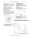
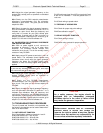
2.3 MOUNTING INSTRUCTIONS
Four mounting holes are provided on the case as
shown in Figure 1. Although the unit can withstand
the normal vibration levels and temperature
excursions encountered, it is a good practice to mount
the unit in a location where these effects are
minimized. The unit should be attached to the
mounting plate with 10-32 screws.
Figure 1. Installation Drawing
3.0 ADDITIONAL FEATURES
3.1 OVERSPEED TRIP TESTING
Overspeed trip testing while the engine is running at
its normal speed can be accomplished by temporarily
connecting terminal 2 to terminal 3. This lowers the
overspeed setpoint of OS-SW2 to 67% of its
set/calibrated value.
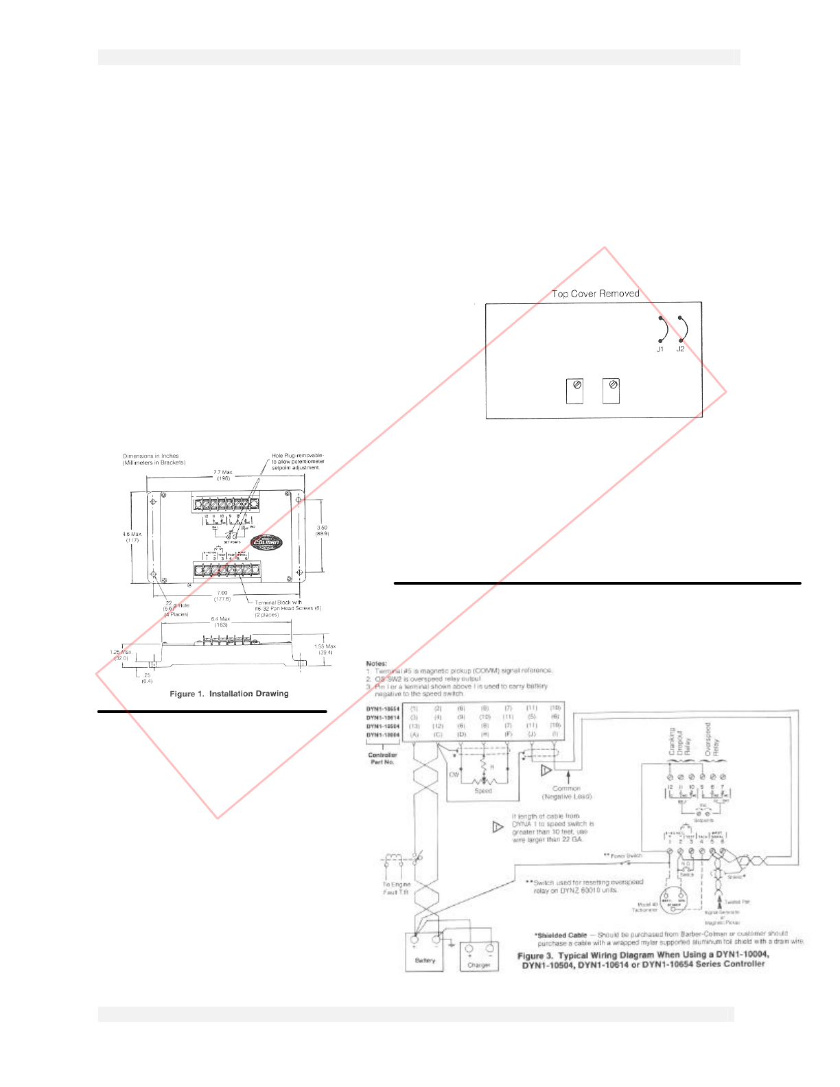
3.2 TACHOMETER READOUT
Tachometer readout can be obtained by connecting a
Synchro-Start Model 40 tachometer to terminals 1, 2
and 4 as shown in Figure 3.
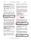
Figure 2
3.3 SW1 & OS-SW2 ADJUSTMENT AND
ADJUSTMENT RANGE
l There are two speed trip setpoint adjustments,
SW1 and OS-SW2, located on top of the unit. Turning
the 20 turn potentiometer adjustment clockwise
increases the RPM setting.
Uncontrolled Document
For Historical Reference Only