


PD-6006/12/24
Power over LAN Solutions 10 Cat. No.: 06-6800-056
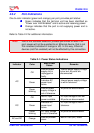
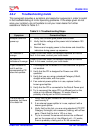
Table 2-2:
Port
Status Indications
Port LED Color Port Load Conditions Port Voltage
Off
Non-active load or
unplugged port.
Power to the port is disconnected.No
DC voltage present on spare pairs.
Green
Active load is plugged in
and complies with
normal load conditions.
Continuous nominal DC voltage is
present on the spare pairs.
Orange
Overload conditions; or
short; or forced external
voltage feed (constant
DC) into the port.
Power to the port is disconnected.
No DC voltage is present on the
spare pairs.
Green blinking
Transitional mode in
which load detection is in
process or discharged
capacitor in the PD.
Power to the port is disconnected.
No DC voltage is present on the
spare pairs.
Orange blinking
Total aggregated power
exceeds pre-defined
power budget.
Power to the port is disconnected.
No DC voltage is present on the
spare pairs.
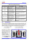
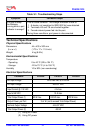
2.4 Connectors
The front panel of the Midspan includes a Console port (DB-9 connector). The
user may connect a terminal and perform software loading, via this connector,
using a standard null modem cable. The console port is set to 19,200-baud, 8
data bits, no parity and 1 stop bit. Pin connections for this connector are:
Pin 2 is Receive (RXD) Pin 3 is Transmit (TXD)
Pin 5 is Ground Pins 1 and 6 are shorted
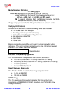
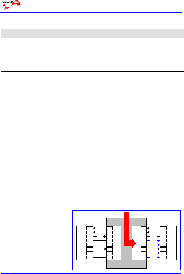
Each data port is configured
as shown in Figure
2-2., as
data route-thru ports for all
data pins (pins 1, 2, 3 and
6).Be certain to use
Category 5 or higher cabling,
as shown in the figure.
Figure
2-2: Connecting to
the Midspan
DC -
1
2
3
4
5
6
7
8
1
2
3
4
5
6
7
8
1
2
3
4
5
6
7
8
1
2
3
4
5
6
7
8
RJ-IN RJ-OUT
Ethernet
Switch
PD
RJ-45
RJ-45
Dat a
Dat a
Dat a
Dat a
Midspan Channel
Power Bus
Dat a
Dat a
Dat a
DC +
Dat a
DC -
DC +