COM128 Installation and Operation Manual Schneider Electric
9
RS-485 PORT
SHLD
SHLD
To next
device
To next
device
RS-485
Device
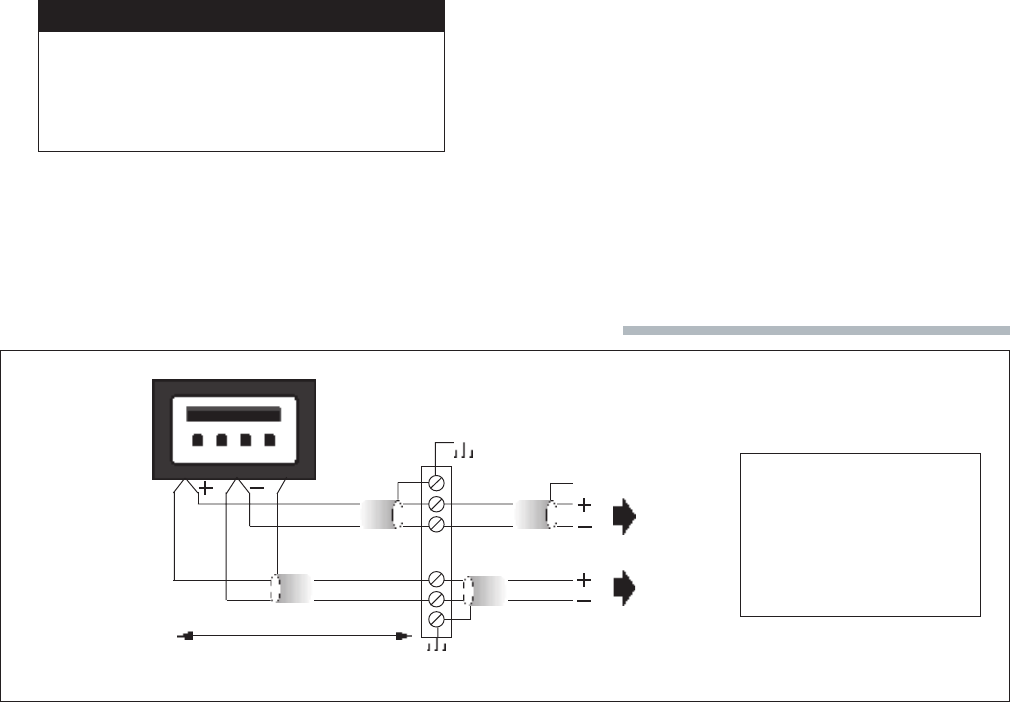
RS-485 Cable
22 gauge shielded
twisted pair
Terminal
Strip
DISTANCE X
NOTE
Terminal strip connection
method adds 2 times
distance X to overall RS-485
cable length.
4.3 RS-485 BUS CONNECTIONS
4.3.1 CONVERTOR CONNECTIONS
The RS-485 port of the COM128 provides screw down,
captured wire type terminal blocks that unplug from the main
chassis to simplify wiring.
Refer to the following sections for detailed information on
wiring requirements and recommended topologies.
4.3.2 GENERAL BUS WIRING
CONSIDERATIONS
Up to 32 devices can be connected on a single RS-485 bus. The
overall length of the RS-485 cable connecting all devices cannot
exceed 4000 ft. (1219 m).
Devices connected on the bus, including convertor(s) and other
instrumentation, must be wired as follows:
a. Use a good quality shielded twisted pair cable for each
RS-485 bus. It is recommended that AWG 22 (0.6 mm) or
larger conductor size be used.
b. Ensure that the polarity is correct when connecting to the
RS-485 port (+) and (-) terminals of each device.
c. The shield of each segment of the RS-485 cable must be
connected to ground at one end only.
CAUTION
Do not connect ground to the shield at both
ends of a segment. Doing so will allow
ground loop currents to flow in the shield,
inducing noise in the communications cable.
d. It is recommended that an intermediate terminal strip be
used to connect each device to the bus. This will allow for
easy removal of a device for servicing if necessary. The
terminal strip should be connected as shown in Figure
4.3.2.
4.3.3 RECOMMENDED TOPOLOGIES
Devices on an RS-485 bus are connected in a point-to-point
configuration, with the (+) and (-) terminals of each device
connected to the associated terminals on the next device. This
is illustrated in Figure 4.3.3a.
While there are many topologies that can be used to connect
devices on an RS-485 communication bus, the two recom-
mended methods are the straight-line and loop topologies.
STRAIGHT-LINE TOPOLOGY
The straight-line wiring method is illustrated in Figure 4.3.3a.
Note that connections are shown for one RS-485 port only. The
COM128 supports four RS-485 buses simultaneously. The
COM128 can exist at any position on the RS-485 bus, including
an end point.
Each end point of the straight-line bus must be terminated with
a 1/4 watt resistor. These termination resistors reduce signal
reflections which may corrupt data on the bus.
Termination resistors are connected between the (+) and (-)
terminals of the device at each end of the bus. This device can
include either a convertor or any other instrument. The value
of the resistor should match the line impedance of the cable
being used. For AWG 22 shielded twisted pair cable, values
between 150 and 300 ohms are typical. Consult the cable
manufacturer’s documentation for the exact impedance of
your cable.
LOOP TOPOLOGY
The loop wiring method is illustrated in Figure 4.3.3a. The
COM128 can exist at any position on the RS-485 bus.
One advantage of the loop topology is that a single open
circuit fault condition anywhere on the loop will not result in
the loss of communication between the computer station and
any of the remote devices.
The loop topology does not require termination resistors at any
point on the bus.
Figure 4.3.2 RS-485 Intermediate Terminal Strip Connection
