


COMMUNICATION
EATON Powerware
®
9355 UPS (10/15 kVA) User’s Guide S 164201594 Rev B www.powerware.com
52
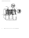
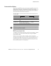
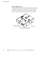
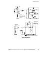
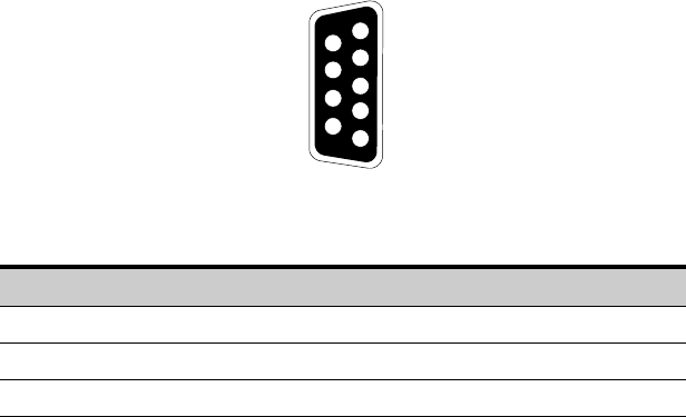
The cable pins are identified in Figure 38 and the pin functions are
described in Table 3. See Figure 33 on page 47 for serial port location.
3
8
7
9
1
6
2
4
5
Figure 38. Communication Port
Table 3. Communication Port Pin Assignment
Pin Number Signal Name Function Direction from the UPS
2 TxD Transmit to external device Out
3 RxD Receive from external device In
5 GND Signal common (tied to chassis) —
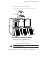
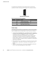
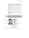
X-Slot Cards
X-Slot cards allow the UPS to communicate in a variety of networking
environments and with different types of devices. The Powerware 9355
has two available communication bays for any X-Slot card, including:
S ConnectUPS -X Web/SNMP Card - has SNMP and HTTP capabilities
as well as monitoring through a Web browser interface; connects to a
twisted-pair Ethernet (10/100BaseT) network. It has a built-in
switching hub that allows three additional network devices to be
connected to the network without the requirement of additional
network drops. In addition, a Powerware Environmental Monitoring
Probe can be attached to obtain humidity, temperature, smoke alarm,
and security information.
S Relay Interface Card - has isolated dry contact (Form-C) relay outputs
for UPS status: Utility failure, Low battery, UPS alarm/OK, or On
bypass.
S Modbus
®
Card - allows you to continuously and reliably monitor the
UPSs in your Building Management System (BMS).
t