


INSTALLATION
EATON Powerware
®
Energy Management System (EMS) Upgrade Kit User’s Guide S 164201724 Rev 1 www.powerware.com
21
C A U T I O N
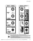
S Panel 1 voltage sensing includes a ground wire, but Panel 2 voltage sensing does not. If
installing dual panels, connect the voltage harness V1 for Panel 1 first. When
disconnecting dual panels, disconnect the voltage harness V2 for Panel 2 first.
S Use the branch circuit breakers to disconnect hazardous voltage from the EMS−UGK. Turn
off the breaker before disconnecting the voltage measuring circuit cables, or hazardous
voltage may be present at the exposed end of the cable.
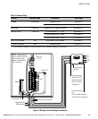
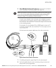
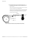
10. On the voltage harness V1 for Panel 1, locate the green and yellow
Ground wire. Attach the Ground ferrule to a ground point within the
panel. See Figure 5 on page 15.
11. Attach the Neutral wire to the Neutral bar in the panel. See Figure 5
on page 15.
C A U T I O N
Before connecting the voltage harness to a branch circuit breaker, shut down the branch
circuit breaker. Risk of electric shock.
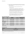
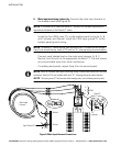
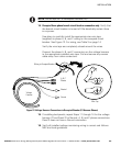
12. Choose an option for connecting the phases for voltage sensing:
NOTE Maximum branch circuit breaker size where the voltage sensing is located is 20A.
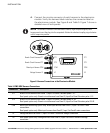
S Use the supplied wire tap transition harnesses to connect the
voltage harness to an unoccupied three−phase branch circuit
breaker (continue to Step 13).
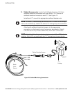
S Use the supplied wire taps to connect the voltage harness to an
occupied three−phase branch circuit breaker (proceed to Step 14
on page 23).