


12
Powerware
®
5115A USB User’s Guide • www.powerware.com.au
Additional UPS Features
Table 1. Communication Port Pin Assignment
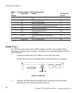
USB Port
The UPS can communicate with a USB-compliant computer using LanSafe Power
Management Software (v5.0 or higher). To establish communication between the UPS
and a computer:
Pin Signal Name Function Direction from
Number the UPS
1 Low Batt Low Battery relay contact; 20 mA, 30 Vdc contact Out
rating
2 RxD Transmit to external device Out
3 TxD Receive from external device In
4 DTR PnP (Plug and Play) from external device (tied to Pin 6) In
5 GND Signal common (tied to chassis) -
6 DSR To external device (tied to Pin 4) Out
7 - No Connection -
8 AC Fail AC Fail relay contact; 20 mA, 30 Vdc contact Out
rating
9 Power Source +V (8 to 24 Volts DC Power) Out
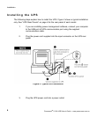
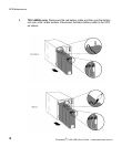
1. Connect the USB cable to the USB port on the UPS rear panel.
Connect the other end of the USB cable to the USB port on your computer.
2. Install the LanSafe software and USB drivers according to the instructions
provided with the Powerware Software Suite CD.
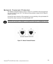
Figure 9. USB Port
USB Port