


Using the Monitor Panel
5−12
EATON Powerware
®
9315 UPS (200–300 kVA) Operation Manual S 164201036 Rev G www.powerware.com
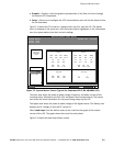
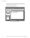
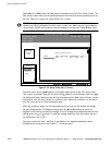
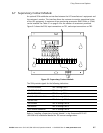
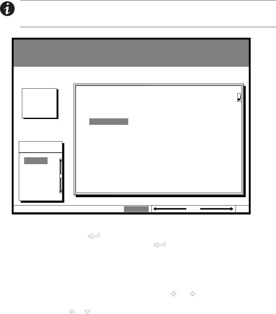
Select Port 1 or Port 2 from the Setup menu to display one of the Port Setup screens. The
Port Setup screens allow you to specify settings for the two serial communication ports on
the UPS. Figure 5-10 shows the Setup Serial Port 1 screen.
NOTE
The X−Slot communication bay is connected internally to the DB−25 port by
default; the DB−25 is disabled for other uses. Contact your Eaton service representative
to purchase, install, and set up an external modem or an internal X−Slot Modem Card.
Statistics Graphics Setup
Setup
Port 1
Uninterruptible Power System
UPS System Normal
Alarm: None
Notice: None
EventsMeters
Setup Serial Port 1
RATE
9600
DATA/STOP
8 1
HANDSHAKING
XON / XOFF
SAVE
NO
Time
MODE
TERMINAL
Port 2
04 NOV 1997 14:23:45
100%
Percent
Battery
Figure 5-10. Setup Serial Port 1 Screen
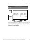
The small return arrow (
) appears in the upper right corner of the Port Setup screen.
This arrow is a reminder that you can press the
button on the Monitor Panel to toggle
the buttons between the menu box and the information area. When the scroll bar is in the
information area, the return arrow is in the menu box. When the scroll bar is in the menu
box, the return arrow is in the information area.
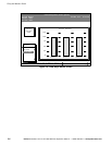
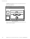
When the scroll bar appears in the information area, you can use the buttons to change
the port configuration. To change a setting, press the
and buttons to move the
highlight to the setting you want to change. To scroll through the available options for that
setting, press the
or button. To save the settings upon exit from this screen, be sure
the SAVE field is set to YES.
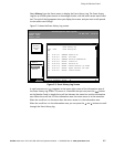
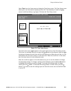
The setup screens for Port 1 and Port 2 are identical. For detailed information about
configuring the serial ports, see Chapter 7, Communication."