


Communication
7−4
EATON Powerware
®
9315 UPS (200–300 kVA) Operation Manual S 164201036 Rev G www.powerware.com
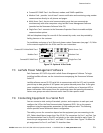
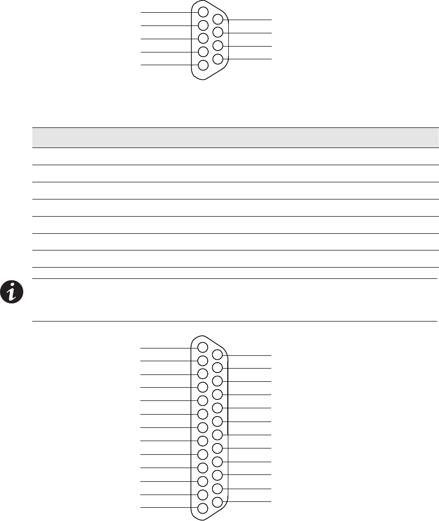
NOT USED
485–
485+
RETURN
7
8
9
1
5
4
3
2
+24V
RS-232 TXD
RS-232 RXD
NOT USED
RETURN
6
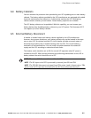
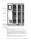
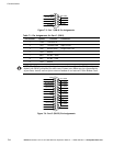
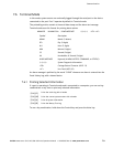
Figure 7-3. Port 1 (DB−9) Pin Assignments
Table 7-1.
Pin Assignments for Port 1 (DB-9)
Pin Number Symbol Function Comments
1 +24V +24 Volts DC
2 TXD Transmit Data Input to UPS
3 RXD Receive Data Output from UPS
5 RTN Return
7 485+ RS-485 + Data
8 485– RS-485 – Data
9 RTN Return
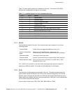
NOTE The X−Slot communication bay is connected internally to the DB−25 port by
default; the DB−25 is disabled for other uses. Contact your Eaton service representative
to purchase, install, and set up an external modem or an internal X−Slot Modem Card.
NOT USED
NOT USED
NOT USED
NOT USED
NOT USED
NOT USED
RS-232 DTR
NOT USED
–12V
NOT USED
NOT USED
NOT USED
23
21
19
17
15
12
1
5
4
3
2
GND
RS-232 TXD
RS-232 RXD
RS-232 RTS
RS-232 CTS
6
10
9
8
7
RS-232 DSR
RTN
+12V
NOT USED
NOT USED
11
13
NOT USED
NOT USED
NOT USED
24
22
25
20
18
16
14
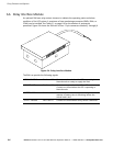
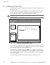
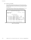
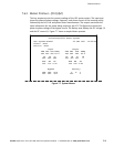
Figure 7-4. Port 2 (DB−25) Pin Assignments